
The Critical Importance of Proper Electric Brake Trailer Wiring
When towing a trailer over 1,500 pounds, relying solely on your tow vehicle’s brakes is a recipe for disaster. Electric brake trailer wiring is the central nervous system that synchronizes your trailer’s braking magnets with your tow vehicle’s brake controller. A poorly executed wiring harness doesn't just risk a blown fuse; it causes uneven braking, jackknifing, and catastrophic failure on steep descents. As of 2026, with the rising weight of modern overlanding and utility trailers, ensuring your electrical infrastructure can handle sustained amperage loads without voltage drop is more critical than ever.
This home project guide bypasses the generic advice found in big-box store manuals. We will dive deep into the exact wire gauges, termination techniques, and diagnostic frameworks required to build a bulletproof 7-way RV blade harness for dual-axle trailers.
Expert Insight: The Grounding Fallacy
Never rely on the hitch ball or safety chains to complete your brake circuit. The #1 cause of erratic trailer braking is a 'floating ground' caused by corrosion at the coupler. Every brake magnet must have a dedicated, independent ground wire terminated directly to the trailer chassis.
The 7-Way RV Blade Pinout & Wire Sizing Matrix
The 7-way RV blade (SAE J2807 compliant) is the undisputed standard for electric brake trailer wiring. However, using the correct wire gauge for each specific circuit is where most DIYers fail. Brake magnets draw significant current; undersizing the wire leads to voltage drop and weak braking.
| Pin Position | Function | Standard Wire Color | Minimum AWG (Copper) | Max Continuous Draw |
|---|---|---|---|---|
| 1 (Top Center) | 12V Auxiliary / Battery Charge | Black | 10 AWG | 30A |
| 2 (Top Right) | Tail / Running Lights | Brown | 12 AWG | 15A |
| 3 (Bottom Right) | Right Turn / Stop | Green | 12 AWG | 10A |
| 4 (Center) | Ground (White) | White | 10 AWG (or 8 AWG) | N/A (Return Path) |
| 5 (Bottom Left) | Left Turn / Stop | Yellow | 12 AWG | 10A |
| 6 (Top Left) | Electric Brakes | Blue | 10 AWG | 20A |
| 7 (Bottom Center) | Backup Lights / Aux | Purple | 14 AWG | 7A |
Note: Always use stranded copper wire (MTW or THHN rated). Solid core wire will fracture under the constant vibration of highway towing.
Essential Materials & 2026 Project Costs
To execute this project to professional standards, you need commercial-grade components. Budget approximately $180 to $250 for a complete dual-axle harness rebuild in 2026, factoring in recent copper price fluctuations.
- Connector: Curt 56226 or Hopkins 48119 7-Way RV Blade (Heavy-duty cast metal housing preferred over molded plastic). ~$25
- Primary Wire: 50ft spool of 10 AWG stranded copper (Blue and White). ~$45
- Secondary Wire: 50ft spool of 12 AWG bonded 4-wire trailer cable (Brown, Green, Yellow, White). ~$35
- Terminations: Adhesive-lined dual-wall heat shrink butt connectors (3:1 shrink ratio) and 10 AWG ring terminals with star washers. ~$25
- Protection: Split loom tubing, UV-rated zip ties, and Permatex 22058 dielectric grease. ~$20
- Tools: Ratcheting wire crimpers (e.g., Knipex 13 88), heat gun, wire strippers, and a digital multimeter.
Step-by-Step Wiring Execution
Step 1: Routing and Securing the Main Harness
Begin at the trailer tongue. Run the 12 AWG bonded lighting cable and the 10 AWG blue brake wire through split loom tubing to protect against road debris. Secure the harness to the interior of the trailer frame rails using UV-rated zip ties every 12 to 18 inches. Crucial: Leave a 24-inch service loop at the tongue to allow for tight turning radii without putting tension on the 7-way plug. Never route wiring near exhaust components or sharp, unpainted metal edges without a rubber grommet.
Step 2: Terminating the 7-Way Plug
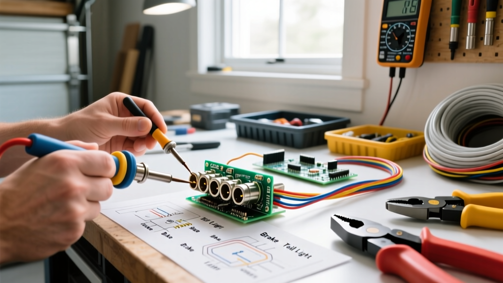
Strip 3/8 inch of insulation from each wire. If your 7-way plug uses set screws (common in heavy-duty metal housings), tin the stripped copper ends with a soldering iron before inserting them into the terminals. This prevents the set screw from fraying the stranded copper, which causes high-resistance hot spots. If using a molded plug with pigtails, use adhesive-lined heat shrink butt connectors. The adhesive lining melts and seals the connection, preventing moisture wicking—a common failure mode that leads to green corrosion inside the wire jacket.
Step 3: Wiring the Brake Magnets & Independent Grounds
Run the 10 AWG blue wire to a central junction block near the axles. From the junction block, use 12 AWG wire to daisy-chain the brake magnets. Do not daisy-chain the grounds. Run an independent 12 AWG white ground wire from each brake magnet directly to the trailer chassis.
Grounding Procedure:
- Use a wire brush or 80-grit sandpaper to remove all paint, rust, and powder coating down to bare steel.
- Attach the 12 AWG ring terminal using a self-tapping sheet metal screw or a drilled hole with a bolt, nut, and star washer (the star washer bites into the metal to ensure a gas-tight electrical connection).
- Smother the terminal in dielectric grease to prevent oxidation.
Tow Vehicle Integration: Brake Controller Setup
Your trailer wiring is only half the equation. The tow vehicle must supply a clean, modulated PWM (Pulse Width Modulation) signal to the blue brake wire. For 2026 DIY installations, the Tekonsha Prodigy P3 (Model 90195) remains the benchmark proportional brake controller, retailing around $170.
According to Tekonsha's official brake controller documentation, the P3 requires a solid 30-amp circuit breaker between the vehicle battery and the controller's black power wire. The blue output wire must be routed through the firewall and connected to the 7-way receptacle's blue pin. If your vehicle features a factory tow package, use the OEM plug-and-play wiring harness located under the dashboard rather than splicing into the vehicle's brake light switch, which can interfere with modern CAN-bus systems and adaptive cruise control.
Diagnostic Troubleshooting Guide
Even with meticulous installation, electrical gremlins can appear. Use this matrix to diagnose common electric brake trailer wiring failures.
| Symptom | Probable Cause | Diagnostic Fix |
|---|---|---|
| Controller displays 'SH' (Short) | Blue brake wire is pinched and shorting to the steel frame. | Inspect wiring near axles and suspension mounts. Look for melted insulation. |
| Brakes feel weak or 'spongy' | Voltage drop due to undersized wire or corroded 7-way plug. | Measure voltage at the trailer plug with brakes applied. It should read >11.5V. Clean plug contacts. |
| Only one axle brakes | Broken daisy-chain wire between axles or failed magnet. | Use a multimeter to check continuity across the two wires at the suspect brake magnet (should read 3-4 Ohms). |
| Lights dim when brakes are applied | Shared ground path or undersized white ground wire. | Upgrade the main 7-way white ground to 8 AWG and ensure chassis grounding points are bare metal. |
Final Safety & Maintenance Checks
Before hitting the road, perform a static breakaway switch test. Pull the breakaway lanyard pin; you should hear a loud, distinct 'clack' from all four brake magnets, and the wheels should be completely locked. If the brakes only hum or hold weakly, your breakaway battery (usually a 12V 5Ah SLA battery mounted on the tongue) is depleted or the wiring bypass is faulty.
For further reading on towing safety standards and electrical requirements, consult the National Highway Traffic Safety Administration (NHTSA) vehicle safety hub, and review the extensive testing data available on etrailer's comprehensive wiring FAQ.
Proper electric brake trailer wiring is not a 'set it and forget it' project. Inspect your 7-way plug for corrosion every six months, re-apply dielectric grease annually, and verify your chassis grounds before every long-haul trip. By adhering to these exact specifications, you ensure your rig stops as predictably and safely as it accelerates.