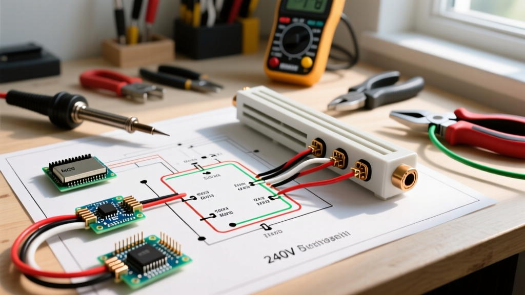

Why Wiring Electric Baseboard Heaters Diagrams Are Your Best Diagnostic Tool
When a baseboard heating system fails in the middle of winter, guessing the fault costs time and money. While a non-contact voltage tester can tell you if power is present, it cannot tell you where the circuit logic has broken down. This is where mastering the interpretation of wiring electric baseboard heaters diagrams becomes critical. These schematics map the exact logical sequence from the breaker panel to the line-side terminals, through the thermostat switching mechanism, and down to the resistive heating elements.
In 2026, the proliferation of smart line-voltage thermostats (like the Mysa V2 or Sinopé TH1400WF) has added low-voltage DC logic boards into traditionally simple AC circuits. Understanding the foundational diagrams is the only way to safely isolate whether a failure lies in the mechanical relay, the solid-state triac, or the heating element itself.
Decoding the Schematic: Key Symbols and Terminals
Before grabbing your Fluke 117 True RMS Multimeter, you must understand the nomenclature used by manufacturers like Cadet, Marley QMark, and King Electric. Most wiring electric baseboard heaters diagrams adhere to NEMA standard schematic symbols.
- L1 and L2 (Line Side): The incoming ungrounded (hot) conductors from the branch circuit breaker. In a 240V system, both carry 120V to ground, 240V phase-to-phase.
- T1 and T2 (Load Side): The outgoing conductors feeding the actual heating element.
- Limit Switch (LS): An automatic, normally-closed (NC) thermal cutoff wired in series with the element. If the heater is blocked by furniture and overheats, this opens the circuit.
- DPST (Double Pole Single Throw): The standard 240V line-voltage thermostat switch type, breaking both L1 and L2 simultaneously for safety.
Expert Insight: Never assume a wall-mounted thermostat diagram matches the built-in end-cap thermostat diagram. A built-in Cadet T410B operates on the exact same 240V principles as a wall-mounted Honeywell CT410B, but the physical terminal block layouts and wire routing paths differ drastically. Always reference the specific schematic taped inside the heater's junction box.
Troubleshooting Matrix: Symptoms vs. Diagram Checkpoints
Use this diagnostic matrix to correlate physical symptoms with specific checkpoints on your wiring electric baseboard heaters diagrams.
| Observed Symptom | Diagram Checkpoint | Multimeter Test Required | Most Likely Culprit |
|---|---|---|---|
| Heater completely dead; breaker holds. | Line-side (L1/L2) at T-stat | AC Voltage (V~) Phase-to-Phase | Tripped GFCI/AFCI upstream, loose neutral/hot in panel. |
| T-stat clicks, but no heat generated. | Load-side (T1/T2) at T-stat | AC Voltage (V~) under load | Failed mechanical T-stat contacts or open thermal limit switch. |
| Breaker trips instantly upon T-stat call. | Element terminals & Ground | Resistance (Ω) & Continuity to Ground | Shorted heating element or pinched wire in junction box. |
| Heater cycles rapidly (short cycling). | Limit Switch (LS) series path | Infrared Thermometer on casing | Blocked airflow tripping the high-limit thermal cutoff. |
Scenario 1: The "Dead" Heater (No Heat, Breaker Not Tripped)
You arrive at a remodel where a 2000W, 240V Marley QMark 2504TW baseboard heater refuses to turn on. The 20A double-pole breaker in the panel is firmly in the ON position.
Step 1: Verify Incoming Power. Remove the thermostat cover. Set your multimeter to AC Voltage. Place one probe on L1 and the other on L2. You should read between 235V and 245V. If you read 0V, the fault is upstream (e.g., a tripped arc-fault breaker hidden in a sub-panel, or a severed cable in the wall). If you read 120V, you have lost one pole of the 240V circuit—often due to a failed breaker bus stab or a loose pigtail in the main panel.
Step 2: Bypass the Thermostat. If L1/L2 show 240V, turn the breaker off. Disconnect the load wires (T1/T2) from the thermostat and splice them directly to the line wires (L1 to T1, L2 to T2) using Wago 221 lever-nuts for a secure, temporary connection. Restore power. If the heater immediately begins radiating heat, the thermostat's internal bimetallic strip or micro-switch has failed and requires replacement.
Scenario 2: Breaker Trips Instantly Upon T-Stat Call
This is a classic dead-short scenario. When you consult the wiring electric baseboard heaters diagrams, you will see the current path flows from L1, through the T-stat, through the thermal limit switch, through the resistive wire element, and back via L2.
The Ohm's Law Verification: A healthy 2000W element at 240V should measure approximately 28.8 Ohms (R = V² / P). Turn off the breaker and isolate the heating element from the circuit wires. Place your multimeter probes on the two element terminals.
- Reading is ~28.8 Ω: The element is healthy. The short is likely in the wiring harness or the thermostat itself.
- Reading is 0.0 Ω to 2.0 Ω: The internal resistive coil has collapsed and shorted upon itself. The element assembly must be replaced.
- Reading is OL (Open Loop): The element has burned open. This will not trip a breaker, but it will result in zero heat output.
The Ground Fault Check: Leave one probe on an element terminal and place the other on the bare copper ground wire or the metal heater chassis. Any reading other than OL indicates the element's magnesium oxide insulation has broken down, allowing current to leak to the chassis. This is a severe shock hazard and mandates immediate element replacement.
Modern Complications: Smart Thermostats and Legacy Diagrams
As of 2026, many homeowners are retrofitting legacy baseboards with Wi-Fi enabled line-voltage thermostats like the Sinopé TH1400WF. These devices require a neutral wire (or a specialized bypass module) to power their internal logic boards and radios.
Standard wiring electric baseboard heaters diagrams for older homes only account for two wires (Line and Load) in the wall box. If you attempt to install a smart thermostat without a neutral, the device will attempt to draw its parasitic operating current through the heating element. Because a 1500W heater has low resistance, this might work, but it often causes the heater to emit a faint, continuous heat even when the thermostat is set to "Off," or it causes the smart thermostat's logic board to brownout and reboot endlessly.
The Fix: If your junction box lacks a neutral (white wire), you must either pull a new 12/3 NM-B cable from the panel to provide a dedicated neutral, or install the manufacturer-provided load bypass module directly at the baseboard heater's junction box, which artificially creates a closed loop for the smart thermostat's micro-current.
NEC Code Requirements for Baseboard Circuits
When troubleshooting and replacing components, all work must comply with the National Electrical Code (NEC). According to NFPA 70 (NEC), Article 424 governs Electric Space-Heating Equipment.
- Branch Circuit Sizing: Baseboard heaters are considered continuous loads if they are expected to run for 3 hours or more. Therefore, a 20A circuit can only be loaded to 16A (3840W at 240V). Never daisy-chain heaters that exceed 80% of the breaker's rating.
- Disconnecting Means: NEC 424.19 requires a disconnecting means to be within sight of the heater or capable of being locked in the open position. Modern smart thermostats often include a physical, air-gap disconnect switch to satisfy this requirement, whereas older dial thermostats do not.
- Clearances: Per manufacturer UL listings and Department of Energy guidelines, baseboard heaters require strict clearance from combustible materials (typically 6 inches to the side and 12 inches above). Blocking these clearances causes the thermal limit switch to cycle, eventually welding the contacts shut or burning out the switch entirely.
Frequently Asked Questions
Can I wire a 120V thermostat to a 240V baseboard heater?
No. Wiring electric baseboard heaters diagrams clearly differentiate between single-pole (120V) and double-pole (240V) configurations. If you use a 120V single-pole thermostat (like a Cadet T410A) on a 240V circuit, it will only break one leg of the circuit. The heater will turn off, but 120V will still be present at the element terminals, creating a lethal shock hazard during maintenance. Furthermore, the internal contacts of a 120V thermostat will arc violently and weld shut if subjected to 240V phase-to-phase voltage.
Why does my baseboard heater hum loudly when turned on?
A 60Hz hum is usually caused by loose mounting brackets or the metal chassis expanding against drywall. However, if the hum is accompanied by a buzzing from the thermostat, the mechanical contacts are arcing. This indicates pitting on the contact surfaces due to high inrush current. Replace the thermostat immediately before it becomes a fire hazard. For silent operation, consider upgrading to a solid-state triac-based smart thermostat, which switches voltage at the zero-crossing point, eliminating mechanical arcing and contact hum.
Is it safe to use wire nuts inside the baseboard heater junction box?
While UL-listed wire nuts are code-compliant, the high-temperature environment inside a baseboard junction box can cause standard vinyl electrical tape to melt and wire nut grease to degrade over a decade. For 2026 best practices, use high-temperature ceramic wire nuts or Wago 221 lever-nuts, which provide a gas-tight, vibration-proof connection that can be visually inspected without unwrapping tape. Always ensure OSHA electrical safety standards are met by verifying dead circuits with a CAT III rated meter before opening any junction box.