
The Hidden Hazards of Closed-Wall Wiring
Once the drywall is hung, mudded, and painted, the electrical rough-in becomes invisible. However, electrical wiring behind drywall remains one of the most critical phases of residential and commercial construction. Non-compliant installations hidden behind finished walls are a leading cause of high-resistance arc faults, electrical fires, and failed final inspections. According to the National Fire Protection Association (NFPA), electrical distribution and lighting equipment is consistently among the top causes of home structure fires. For electrical inspectors, contractors, and homeowners conducting retrofit assessments, understanding the National Electrical Code (NEC) requirements for concealed wiring is non-negotiable.
This guide breaks down the exact NEC compliance metrics for concealed Nonmetallic-Sheathed Cable (NM-B, commonly known as Romex), framing hole tolerances, physical protection requirements, and the modern diagnostic tools used to inspect wiring without tearing down finished walls.
NEC 300.4: The 1-1/4 Inch Setback Rule and Nail Plates
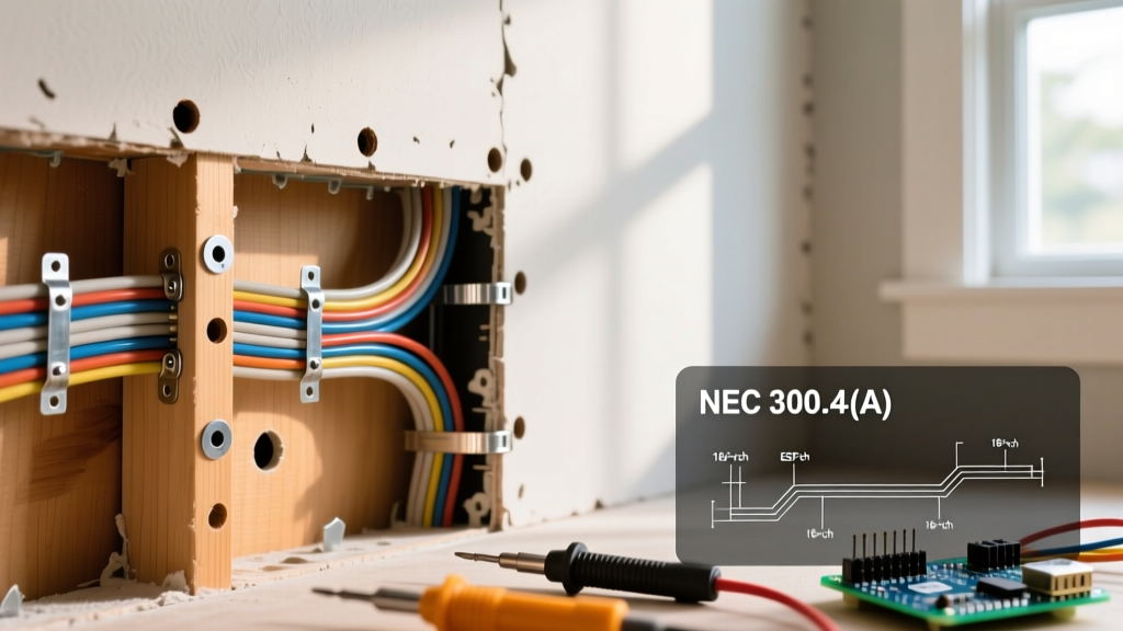
The most frequently violated code section regarding concealed wiring is NEC 300.4(A)(1), which mandates protection against physical damage from nails and screws. Standard 1/2-inch drywall is typically secured using 1-1/4-inch coarse-thread drywall screws, while 5/8-inch fire-rated drywall requires 1-5/8-inch screws. If a cable is run through a hole bored too close to the face of the stud, a drywall screw can easily pierce the NM-B jacket, grazing or severing the copper conductor.
NEC 300.4(A)(1) Summary: Cables and raceways installed through bored holes in framing members must have a minimum clearance of 1-1/4 inches (32 mm) from the nearest edge of the stud. If this 1-1/4 inch setback cannot be maintained, the cable must be protected by a steel plate or sleeve at least 1/16 inch (1.6 mm) thick.
During an inspection, if an inspector uses a borescope and identifies a wire within 1 inch of the stud face without a nail plate, it is an automatic fail. Contractors must use approved steel nail plates, such as the Gardner Bender 1-1/2 in. Steel Nail Plate (Model NP-150) or equivalent 16-gauge steel plates, centered over the cable to deflect drywall screws.
Stud Boring Limits: A Compliance Matrix
When routing electrical wiring behind drywall through wall cavities, the structural integrity of the framing must be maintained. NEC 300.4(A)(1) and the International Residential Code (IRC) dictate strict limits on the size and location of bored holes. Over-boring weakens load-bearing walls and compromises fire-blocking.
| Stud Type | Minimum Edge Distance | Maximum Hole Diameter (2x4 Stud) | Maximum Hole Diameter (2x6 Stud) |
|---|---|---|---|
| Exterior Load-Bearing | 1-1/4 inches | 2-3/8 inches (60% of width) | 3-1/2 inches (60% of width) |
| Interior Load-Bearing | 1-1/4 inches (or 5/8 in. with steel plate) | 2-3/8 inches (60% of width) | 3-1/2 inches (60% of width) |
| Non-Load-Bearing | 5/8 inch | 3-1/2 inches (85% of width) | 4-3/4 inches (85% of width) |
Note: Holes in bearing studs must not be located in the same section as a cut or notch, and the distance between two bored holes must be at least twice the diameter of the larger hole.
Securing and Supporting: NEC 334.30 Requirements
Wiring cannot simply be fished behind drywall without proper support, except in specific retrofit scenarios (NEC 334.10). For new construction or open-wall remodels, NM-B cable must be securely fastened. Inspectors look for two primary metrics behind the drywall:
- Box Support: Cables must be secured within 8 inches of a single-gang device box (without internal cable clamps) or within 12 inches of a box with internal clamps.
- Run Intervals: Cables must be stapled or secured at intervals not exceeding 4-1/2 feet (54 inches).
- Staple Sizing: Using the wrong staple is a major code violation. A 14/2 or 12/2 NM cable requires a 1/2-inch wide staple. Using a narrow 3/8-inch staple can crush the cable jacket, deforming the internal THHN insulation and creating a localized hot spot that thermal imaging will later detect.
Post-Drywall Inspection: Modern Diagnostic Tools
Historically, verifying electrical wiring behind drywall required destructive testing—cutting exploratory holes in the finished wall. In 2026, inspectors and forensic electricians rely on non-destructive evaluation (NDE) tools to verify compliance and diagnose faults.
1. Industrial Borescopes and Endoscopes
To verify nail plate placement and staple spacing without removing drywall, inspectors drill a 1/2-inch hole in an inconspicuous area (like the back of a closet) and insert a borescope. The Ridgid micro CA-350 (priced around $450) features a 3.9mm articulating lens and dual LEDs, allowing inspectors to look up and down the stud bay to verify the 1-1/4 inch setback. For budget-conscious DIY inspections, the Teslong NTS500 (~$85) offers adequate resolution for basic clearance checks.
2. Thermal Imaging Cameras
Thermal cameras detect the heat generated by high-resistance connections or crushed wires. If a drywall screw has partially pierced a conductor, the localized resistance will generate heat under load. The FLIR C5 Compact Thermal Camera (approx. $449) offers 160 x 120 pixel resolution and MSX image enhancement, making it sensitive enough to detect a 2°F to 3°F temperature rise on a 15-amp circuit hidden behind 5/8-inch drywall. According to the U.S. Consumer Product Safety Commission (CPSC), identifying these micro-hotspots before they ignite surrounding wood framing is critical for home fire prevention.
3. Time Domain Reflectometry (TDR)
For long concealed runs where physical damage is suspected but not localized, TDR devices send a pulse down the wire and measure the reflection. A crushed cable behind drywall alters the impedance, allowing the TDR to pinpoint the exact distance to the damage (e.g., 'Fault detected at 34.5 feet'), saving hours of exploratory demolition.
Common Failure Modes Found During Retrofit Inspections
When inspecting older homes or evaluating contractor work behind finished walls, these specific failure modes are the most prevalent:
- The 'Screw-Graze' Arc Fault: A drywall screw pierces the outer jacket and barely touches the copper. It doesn't trip the breaker immediately. Over time, vibration and thermal expansion cause the screw to arc against the copper, eventually carbonizing the drywall paper and igniting.
- Missing Fire-Stopping: Wires running through top and bottom plates of walls must have the holes sealed with fire-rated caulk or expanding foam (like 3M Fire Barrier Sealant) to prevent the wall cavity from acting as a chimney during a fire.
- Over-Stuffed Device Boxes: While technically inside the box, wires pushed aggressively behind the drywall mud ring can cause the drywall to bow, cracking the finish and putting undue mechanical stress on the terminal screws.
- Improper Notching: Instead of boring a hole, lazy contractors notch the edge of a load-bearing stud to run the wire. This violates IRC structural codes and NEC 300.4, severely compromising the wall's load capacity.
Final Compliance Takeaways
Inspecting electrical wiring behind drywall requires a blend of code knowledge and modern diagnostic technology. Whether you are a rough-in electrician ensuring your work will pass the final municipal inspection, or a home inspector evaluating a new build, adherence to the 1-1/4 inch setback rule, proper stud boring limits, and correct cable support intervals is mandatory. When walls are already closed, leveraging borescopes and thermal imaging ensures that what you cannot see will not compromise the safety of the structure.
For further reading on electrical safety standards and contractor guidelines, refer to the International Association of Electrical Inspectors (IAEI) for ongoing code updates and field inspection case studies.