
The Anatomy of a 7-Way Electric Brake Harness
Upgrading or building a custom trailer harness is one of the most rewarding DIY automotive projects you can tackle, but it leaves zero room for error. When you are handling wiring for trailer with electric brakes, you are managing high-current circuits that dictate your stopping power on the highway. While standard 4-way flat connectors handle basic lighting, any trailer equipped with electric drum brakes requires a 7-way RV blade connector to accommodate the dedicated brake output circuit, a 12V auxiliary charge line, and reverse lights.
According to safety regulations outlined by the National Highway Traffic Safety Administration (NHTSA), trailers exceeding specific weight thresholds (often 1,500 to 3,000 lbs depending on your state) must be equipped with independent braking systems. This guide bypasses the generic advice found in big-box store pamphlets and dives deep into the exact wire gauges, routing protocols, and failure-mode preventions required for a bulletproof 7-way setup in 2026.
Wire Selection: Why THHN Fails and SAE J1128 Wins
The most common mistake DIYers make is pulling standard PVC-insulated THHN wire from their home electrical spool to wire a trailer. THHN is designed for static, climate-controlled conduit. On a trailer, it will crack under UV exposure, shatter in sub-zero temperatures, and melt near exhaust routing.
For professional-grade wiring for trailer with electric brakes, you must use cross-linked polyethylene (XLPE) insulated wire that meets SAE International J1128 or J1127 standards. This wire is rated for extreme temperature swings (-40°C to 125°C), resists road salt, and features a much thinner insulation wall, allowing more copper strands in the same gauge.
The 2026 Gauge Sizing Matrix
| Circuit Function | Standard Color | Minimum AWG | Pro-Tier AWG (30ft+ Trailers) |
|---|---|---|---|
| Electric Brakes (Blue) | Blue | 10 AWG | 8 AWG |
| Ground (White) | White | 10 AWG | 8 AWG |
| 12V Auxiliary Charge | Red or Black | 10 AWG | 8 AWG |
| Tail / Running Lights | Brown | 12 AWG | 12 AWG |
| Left Turn / Stop | Yellow | 12 AWG | 12 AWG |
| Right Turn / Stop | Green | 12 AWG | 12 AWG |
| Reverse Lights | Purple | 14 AWG | 12 AWG |
Note on Voltage Drop: Electric brake magnets draw roughly 12 amps per wheel. A dual-axle trailer pulls 24 amps. Over a 30-foot run (60 feet round-trip), 10 AWG wire will experience a ~1.44V drop, delivering only 10.56V to the magnets. Upsizing the blue brake wire and white ground wire to 8 AWG reduces this drop to 0.9V, ensuring faster, harder brake engagement.
7-Way RV Blade Pinout & Routing Protocol
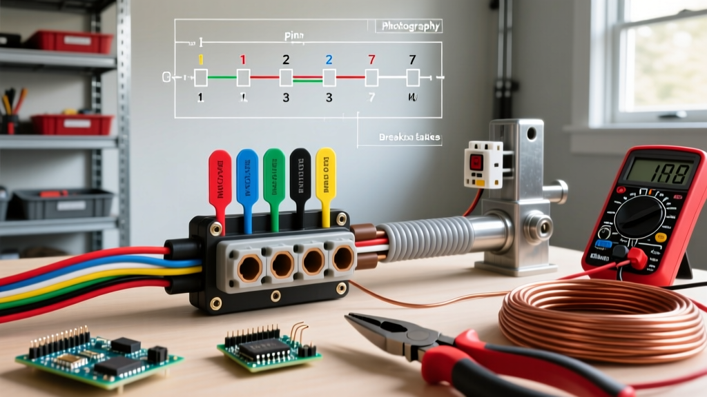
Before cutting any wire, map your 7-way plug. The industry-standard RV blade pinout (viewed from the wiring side of the plug) is as follows:
- Top Left: Left Turn/Stop (Yellow)
- Top Right: Reverse Lights (Purple)
- Bottom Left: Ground (White)
- Bottom Right: Right Turn/Stop (Green)
- Center Left: Tail/Running Lights (Brown)
- Center Right: Electric Brakes (Blue)
- Bottom Center: 12V Auxiliary (Red/Black)
Step 1: Harness Routing and Looming
Never run bare wire along the trailer tongue. Bundle your wires inside a split-loom corrugated tubing or, ideally, a sealed nylon braided sleeve. Secure the loom every 12 inches using UV-rated zip ties or stainless steel P-clips. Keep the harness at least 6 inches away from any moving suspension components and avoid routing it directly over the axle where road debris impact is highest.
Step 2: Splicing and Termination
Abandon twist-connectors and electrical tape. The vibration of towing will shake twist-connectors loose within 500 miles. For every splice in your wiring for trailer with electric brakes harness, use a butt connector crimped with a proper ratcheting crimp tool, followed by adhesive-lined marine heat shrink (such as 3M MDT). When heated, the inner lining melts and seals out moisture, preventing the green corrosion that causes ghost-braking.
Step 3: The Grounding Point (The #1 Failure Mode)
The white ground wire must be terminated to the trailer frame using a heavy-duty ring terminal. Do not just screw it into painted metal. Use a wire brush or sandpaper to grind away paint, powder coat, or rust down to bare, shiny steel. Secure the ring terminal with a stainless steel bolt and a star washer (which bites into the metal). Finally, smother the connection in dielectric grease to prevent oxidation.
The Breakaway Switch: Wiring It Correctly
CRITICAL SAFETY ALERT: A shocking number of DIYers wire the breakaway switch's power feed to the 12V auxiliary pin on the 7-way plug. This is a fatal flaw. If the trailer uncouples from the truck, the 7-way plug severs, cutting power to the breakaway switch exactly when you need it to apply the trailer brakes. The breakaway switch MUST be wired directly to the trailer's onboard 12V battery.
Breakaway Wiring Logic
- Run a dedicated 12 AWG red wire from the positive terminal of the trailer's onboard breakaway battery directly to one side of the breakaway switch.
- Run a second 12 AWG black wire from the other side of the breakaway switch and splice it directly into the Blue (Electric Brake) wire, between the 7-way plug and the trailer's brake axles.
- When the pin is pulled, the switch closes, sending 12V from the trailer battery directly to the brake magnets, locking the wheels independently of the tow vehicle.
2026 Component Cost & Tool Breakdown
Building a reliable harness requires an upfront investment in quality components. Here is what you should expect to spend for a premium dual-axle setup:
| Component | Recommended Spec / Model | Est. 2026 Cost |
|---|---|---|
| 7-Way Molded Plug | Polling Industries 50-6700 (8ft pigtail) | $35.00 - $45.00 |
| Primary Wire (XLPE) | 10 AWG & 12 AWG SAE J1128 (per ft) | $0.80 - $1.20 / ft |
| Brake Controller (Tow Vehicle) | Tekonsha Prodigy P3 (Model 90195) | $165.00 - $185.00 |
| Breakaway Kit | Curt 20005 (with 4Ah battery) | $25.00 - $35.00 |
| Adhesive Heat Shrink | 3M MDT Dual-Wall Assortment | $20.00 - $30.00 |
| Ratcheting Crimper | Knipex 97 51 12 or Titan 11500 | $45.00 - $90.00 |
For brake controller installation and gain calibration, always refer to the specific Tekonsha or Curt manufacturer guides, as improper gain settings can lead to premature magnet wear or trailer wheel lockup.
Advanced Troubleshooting: Edge Cases & Failure Modes
Even with perfect execution, environmental factors can introduce gremlins into your wiring for trailer with electric brakes. Here is how to diagnose the most common advanced issues:
1. Ghost Braking or Pulsing Brakes
Symptom: The trailer brakes apply lightly while driving on the highway without the truck's brake pedal being pressed.
Diagnosis: This is almost always caused by a short between the Blue (brake) wire and the Brown (tail light) or Red (12V aux) wire. As the harness vibrates, a compromised insulation barrier allows 12V to bleed into the brake circuit. Strip back the loom at the trailer tongue hinge point (the highest flex zone) and inspect for pinch points.
2. Tail Lights Flicker When Brakes Apply
Symptom: Hitting the brake pedal causes the trailer's running lights to dim or strobe.
Diagnosis: You have a 'ground bounce' issue. The brake magnets are drawing 24 amps, but the white ground wire cannot handle the return current, so the electricity backfeeds through the tail light ground wires to find a path back to the truck. Sand your main frame ground point and upgrade the white wire to 8 AWG.
3. Breakaway Switch Fails to Lock Brakes
Symptom: Pulling the pin during a stationary test yields zero brake engagement.
Diagnosis: First, check the inline fuse on the breakaway battery feed. Second, test the micro-switch inside the breakaway housing with a multimeter for continuity when the pin is pulled. Finally, verify the trailer battery is holding at least 12.4V; a sulfated or deeply discharged breakaway battery will not generate the amperage required to pull the brake magnets.
Final Inspection Checklist
Before taking your newly wired trailer onto public roads, perform this 5-minute bench test:
- Plug the 7-way into the tow vehicle with the engine running.
- Verify all running, turn, and reverse lights illuminate correctly.
- Have an assistant press the brake pedal while you manually spin the trailer tires; they should exhibit heavy resistance.
- Use the manual override slide on your in-cabin brake controller to verify the blue circuit is hot independent of the brake pedal switch.
- Pull the breakaway pin and attempt to spin the wheels; they must lock up immediately.
By adhering to SAE wire standards, executing marine-grade terminations, and isolating your breakaway power feed, your trailer's braking system will remain reliable, safe, and legal for thousands of miles of towing.