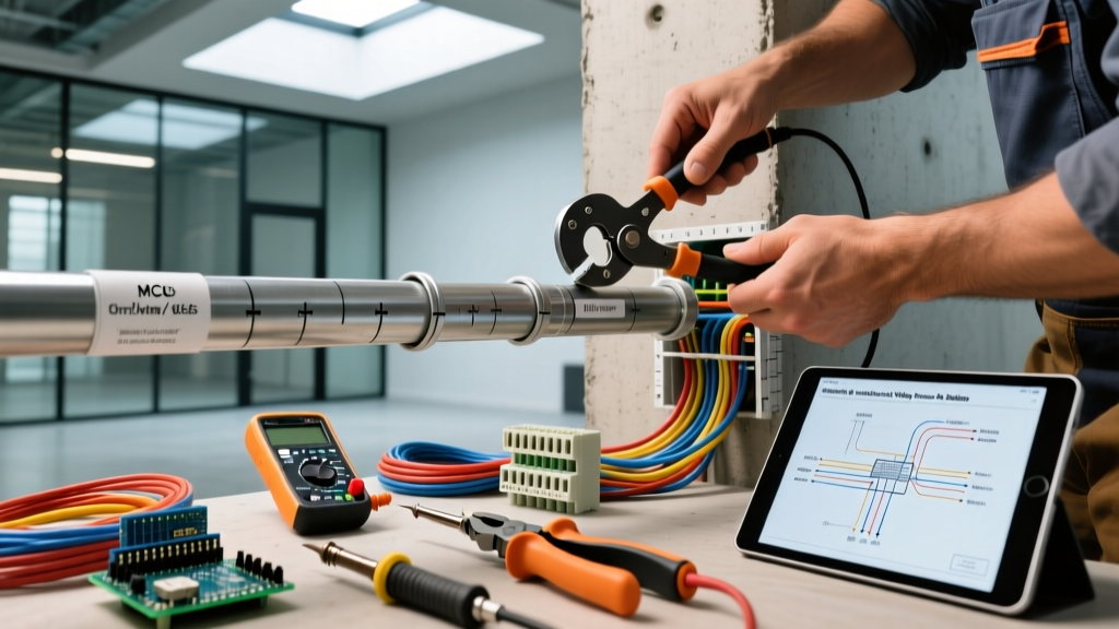

The Commercial Electrical Wiring Process: Beyond Residential Basics
The commercial electrical wiring process is fundamentally different from residential wiring. While a home relies on 120/240V single-phase power and non-metallic (NM) sheathed cable, commercial facilities demand 3-phase power systems (typically 480Y/277V or 208Y/120V), metal raceways, and rigorous adherence to the National Electrical Code (NEC). Whether you are wiring a 10,000-square-foot retail space or a multi-story office complex, the stakes are higher, the load calculations are more complex, and the margin for error is virtually zero.
In 2026, commercial electrical contractors must also navigate advanced energy codes, integrated building automation systems, and strict safety protocols. According to the Occupational Safety and Health Administration (OSHA), electrical hazards remain a leading cause of workplace fatalities, making precise execution of the commercial wiring sequence a matter of life and death.
This comprehensive guide breaks down the commercial electrical wiring process into five actionable phases, providing the deep technical specifications required for modern construction.
Phase 1: Blueprint Analysis and Load Calculations
Before a single piece of conduit is cut, the electrical team must dissect the architectural and mechanical blueprints. The cornerstone of this phase is the load calculation, governed by NEC Article 220.
Handling Non-Linear Loads and Harmonics
Modern commercial buildings are saturated with non-linear loads—LED drivers, variable frequency drives (VFDs), and server racks. These devices generate harmonic distortion, which can overheat neutral conductors and transformers.
- Neutral Sizing: For feeders supplying electronic equipment, NEC Article 220.61 often requires the neutral conductor to be sized at 100% to 130% of the phase conductor capacity, rather than the traditional derating allowed for linear loads.
- K-Rated Transformers: Specify K-4, K-9, or K-13 rated transformers depending on the harmonic profile. A standard transformer will overheat and fail prematurely under heavy non-linear loading.
Expert Insight: Always cross-reference the HVAC mechanical schedules with your electrical panel schedules. A 20-ton rooftop unit (RTU) might require a 480V, 3-phase, 60A disconnect, but the startup inrush current (LRA) could cause voltage dips if the feeder transformer isn't sized with adequate impedance headroom.
Phase 2: Raceway Selection and Rough-In
Unlike residential stub-outs, commercial wiring relies heavily on metallic raceways to protect conductors from physical damage and electromagnetic interference (EMI). The rough-in phase typically accounts for 40% of the total labor hours in the commercial electrical wiring process.
Conduit Comparison Matrix
Selecting the correct raceway is dictated by the environment and local amendments to the NEC. Below is a breakdown of the most common commercial conduits:
| Conduit Type | NEC Article | Wall Thickness | Avg. Cost (per 10ft) | Primary Commercial Application |
|---|---|---|---|---|
| EMT (Electrical Metallic Tubing) | Article 358 | Thin (approx. 0.065") | $12 - $18 | Interior dry locations, above drop ceilings |
| IMC (Intermediate Metal Conduit) | Article 345 | Medium (approx. 0.120") | $28 - $35 | Exterior walls, parking garages, light exposure |
| RMC (Rigid Metal Conduit) | Article 344 | Thick (approx. 0.180") | $65 - $85 | Embedded in concrete, severe physical damage zones |
| PVC (Schedule 80) | Article 352 | Variable | $20 - $30 | Underground duct banks, highly corrosive environments |
Bending Offsets and Fill Capacity
When routing EMT or RMC, adhere strictly to NEC Chapter 9, Table 1, which limits conduit fill to 40% for three or more conductors. Furthermore, when calculating offsets, maintain the minimum bending radius. For a 2-inch EMT conduit, the minimum bend radius is 6 inches. Using a hickey bender instead of a mechanical ratchet or hydraulic bender on conduits larger than 1 inch will result in kinking, violating code and destroying the wire pulling path.
Phase 3: Wire Pulling and Conductor Management
Once the raceway system is continuous and properly grounded, the wire pulling phase begins. Commercial feeders frequently utilize XHHW-2 or THHN/THWN-2 copper or aluminum conductors.
Managing Pulling Tension and Jam Ratios
Pulling 350 kcmil conductors through a 200-foot run of 3-inch conduit requires meticulous planning. Exceeding the maximum pulling tension will stretch the copper, altering its metallurgical properties and increasing resistance.
- Calculate Maximum Pulling Tension: Use the formula T = L x w x f x n (where L is length, w is weight per foot, f is friction coefficient, and n is the number of conductors). For copper, the maximum pulling tension is 0.008 lbs per circular mil.
- Check the Jam Ratio: When pulling three conductors through a conduit, calculate the jam ratio using D/d (Conduit Inside Diameter / Conductor Outside Diameter). If the ratio falls between 2.8 and 3.2, the cables can jam at the bend. Upsize the conduit or use a different pulling configuration.
- Apply Pulling Compound: Never pull dry. Use a high-performance lubricant like Polywater J or 3M Wire Pulling Compound. Apply it directly to the conductors and inside the conduit mouth to reduce the friction coefficient from 0.5 to roughly 0.15.
Phase 4: Terminations and Torque Specifications
The most common point of failure in any commercial electrical system is a loose termination. Loose connections create high-resistance joints, leading to localized heating, arcing, and ultimately, catastrophic fires.
The NEC 110.14(D) Mandate
Modern code cycles strictly enforce the use of calibrated torque tools. You can no longer rely on the "feel" of a standard screwdriver. For commercial panelboards and disconnects, you must use a calibrated torque screwdriver (for values under 100 in-lbs) or a torque wrench (for values above 100 in-lbs).
For example, terminating a 500 kcmil aluminum feeder on a 400A main breaker lug typically requires a torque value between 350 and 450 in-lbs, depending on the manufacturer's specifications (e.g., Eaton or Square D). Always consult the specific equipment data sheet, as manufacturer instructions supersede general code tables per NEC 110.3(B).
Phase 5: Testing, Commissioning, and Inspection
The final stage of the commercial electrical wiring process ensures the system is safe, functional, and compliant before the utility company grants permanent power. According to the National Fire Protection Association (NFPA), rigorous testing is non-negotiable for commercial occupancies.
Critical Pre-Energization Tests
- Insulation Resistance Testing (Megger Testing): Before energizing, apply a DC voltage (typically 500V or 1000V for 600V-rated systems) using a Megohmmeter to test the integrity of the wire insulation. A reading below 1 Megohm indicates damaged insulation, likely caused by abrasion during the pulling phase or moisture ingress.
- Continuity and Phasing Checks: Verify that L1, L2, and L3 are correctly phased at every motor starter and RTU disconnect. Reverse phasing on a 3-phase HVAC compressor will cause it to run backward, destroying the scroll mechanism within minutes.
- Infrared Thermography: Once the system is loaded, hire a certified thermographer to scan all panelboards and switchgear. Hot spots (temperature anomalies exceeding 15°F above ambient or adjacent phases) indicate loose terminations that must be re-torqued immediately.
Integrating Energy Efficiency and Smart Controls
In 2026, the commercial electrical wiring process is incomplete without integrating advanced lighting controls and building management systems (BMS). The U.S. Department of Energy (DOE) emphasizes that commercial buildings account for nearly 20% of total U.S. energy consumption, making electrical efficiency a primary design driver.
When wiring commercial lighting, run separate 277V switched legs and low-voltage (0-10V or DALI) control wires. Keep the low-voltage DALI (Digital Addressable Lighting Interface) communication cables separated from the 277V power conductors by at least 2 inches, or use a physical divider in the raceway, to prevent EMI from corrupting the lighting control signals.
Summary of Best Practices
Executing a flawless commercial electrical wiring process requires a synthesis of code knowledge, mechanical precision, and rigorous testing. By respecting conduit fill limits, adhering to strict torque specifications, and anticipating the thermal impacts of non-linear loads, electrical professionals can deliver infrastructure that is safe, resilient, and built to last for decades.