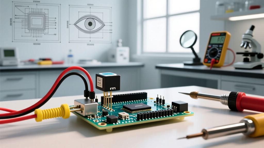

The Compliance Gap: Prototyping vs. Production
When transitioning an electronics project from a hobbyist workbench to a commercial product, educational laboratory, or industrial control panel, the standards for wiring change drastically. Arduino potentiometer wiring is often treated as an afterthought in maker spaces, relying on cheap breadboard jumper wires and loose Dupont connectors. However, in 2026, any low-voltage control circuit integrated into a certified enclosure or lab environment is subject to rigorous safety and functional inspections. Failing to adhere to established wiring codes and termination standards can result in failed UL certifications, rejected lab safety audits, or catastrophic signal degradation in industrial settings.
This guide bridges the gap between basic microcontroller tutorials and professional electrical compliance, focusing on the specific inspection criteria that QA engineers, UL field representatives, and lab safety officers use when evaluating low-voltage analog sensor wiring.
NEC Article 725: Routing Low-Voltage Logic in Mixed Panels
When an Arduino-based control system is mounted inside a panel that also houses 120VAC or 240VAC power supplies, motor contactors, or variable frequency drives (VFDs), the wiring must comply with the National Electrical Code (NEC). Specifically, NFPA 70 (NEC) Article 725 governs Class 1, Class 2, and Class 3 remote-control, signaling, and power-limited circuits.
Separation and Barrier Requirements
The 5V DC wiring used for an Arduino potentiometer circuit qualifies as a Class 2 or Class 3 circuit, depending on the power supply's current-limiting certification. Inspectors will immediately flag any setup where Class 2 logic wires share the same wire duct or conduit as Class 1 (line voltage) wires without proper separation.
- Minimum Separation: Maintain at least a 2-inch (50mm) clearance between unshielded 5V Arduino wiring and 120V/240V AC power lines.
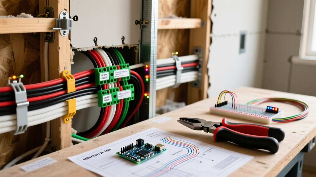
- Grounded Barriers: If the 2-inch clearance cannot be maintained due to panel space constraints, a grounded metal barrier or a dedicated, grounded metallic wire duct must separate the low-voltage analog signals from the high-voltage lines.
- Intersection Routing: When 5V signal wires must cross 120V power wires, they must do so at a strict 90-degree angle to minimize capacitive coupling and electromagnetic interference (EMI).
Component Selection: ADC Impedance and Potentiometer Specs
Functional compliance is just as critical as physical safety. A common failure point during QA testing of Arduino potentiometer wiring is erratic analog-to-digital converter (ADC) readings. This is rarely a software bug; it is usually an impedance mismatch that violates the microcontroller's hardware specifications.
Engineering Insight: The ATmega328P (used in the Arduino Uno Rev3) features a sample-and-hold capacitor in its ADC circuit. For accurate 10-bit resolution, the analog source impedance must be 10kΩ or less. Using a standard 100kΩ hobbyist potentiometer will result in incomplete capacitor charging during the sampling window, causing non-linear and noisy readings that will fail functional inspection.
Approved Components for Inspected Environments
For professional and lab-compliant builds, abandon the cheap, open-frame blue 10kΩ trimmers. Instead, specify sealed, panel-mount precision potentiometers:
- Bourns 3590 Series (Wirewound): 10-turn precision, 2W power rating, ±0.25% linearity. Ideal for manual calibration dials on lab equipment.
- Bourns 3852 Series (Conductive Plastic): Infinite resolution, excellent rotational life (up to 100,000 cycles), and strict 10kΩ resistance variants to perfectly match the ATmega328P ADC impedance requirements.
Wire Selection and Insulation Matrix
Inspection authorities, including OSHA compliance officers evaluating lab environments, require wiring to be rated for the environment and properly identified. Standard PVC jumper wires lack the mechanical strength, chemical resistance, and flammability ratings required for permanent installations.
| Wire Type | AWG | Insulation Material | Temperature Rating | Compliance Use Case |
|---|---|---|---|---|
| Hook-Up Wire (UL1007) | 24 AWG | PVC | 80°C | General internal panel wiring, educational lab kits. |
| High-Temp (UL1332) | 24 AWG | FEP (Fluoropolymer) | 200°C | Enclosures near heat sinks, VFDs, or power resistors. |
| Shielded Twisted Pair | 22 AWG (2-core) | PVC + Aluminum Mylar | 105°C | Long-run potentiometer wiring (>12 inches) to prevent EMI. |
| PTFE Mil-Spec | 26 AWG | PTFE (Teflon) | 200°C+ | Aerospace, medical prototypes, high-density PCB routing. |
IPC-A-610 and IEC 60947: Termination Criteria for Inspectors
The physical termination of the potentiometer wires to the Arduino shield, custom PCB, or terminal block is where the majority of visual inspection failures occur. Inspectors use the IPC-A-610 standard for electronic assemblies and IEC 60947-1 for low-voltage switchgear and controlgear.
The Solder Tinning Ban in Screw Terminals
One of the most frequent mistakes in Arduino wiring is tinning (applying solder to) the stripped ends of stranded wire before inserting them into a screw terminal block (such as the ubiquitous Phoenix Contact MSTB 2.5 series). This is a critical compliance violation.
Solder is subject to 'cold flow' (creep) under mechanical pressure. Over time, and through thermal cycling, the solder will deform, causing the screw terminal to lose torque. This results in a high-resistance connection, voltage drops, and potential arcing. Under IEC standards, stranded wires entering screw terminals must be terminated with crimped wire ferrules (e.g., Phoenix Contact AI 0,5-8 WH for 20 AWG wire).
Visual Solder Joint Inspection (IPC Class 2 vs. Class 3)
If the potentiometer is wired directly to a custom Arduino shield or PCB, the solder joints must meet IPC-A-610 criteria:
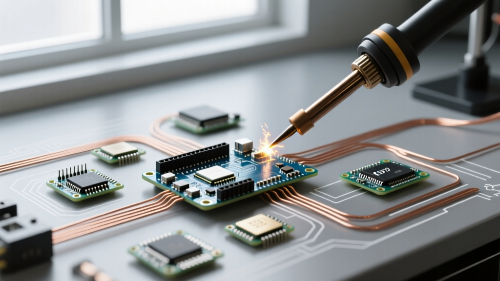
- Wetting Angle: The solder must form a smooth, concave fillet with a wetting angle of less than 90 degrees. Bulbous or convex joints indicate a cold solder joint and will be rejected.
- Wire Strand Integrity: When stripping the wire to connect to the potentiometer lugs, no copper strands may be nicked, scraped, or severed. A single nicked strand reduces the mechanical tensile strength and fails Class 3 inspection.
- Thermal Protection: Heat shrink tubing (minimum 3:1 shrink ratio, dual-wall with adhesive lining) must be applied over the potentiometer lugs to prevent accidental short circuits against the metal panel enclosure.
Signal Integrity and EMC Compliance
In industrial or medical lab environments, the Arduino must pass Electromagnetic Compatibility (EMC) testing. The high-impedance nature of potentiometer wiper signals makes them highly susceptible to picking up 60Hz mains hum and high-frequency switching noise from nearby DC-DC converters.
Guard Rings and Twisted Pairs
To pass EMC inspections, implement the following wiring techniques:
- Twisted Pair Routing: The wiper signal wire and the analog ground (AGND) wire must be twisted together at a rate of at least 4 twists per inch. This ensures that any induced electromagnetic noise appears as common-mode noise, which the ADC's internal differential sampling can reject.
- Guard Rings on PCBs: If the Arduino shield routes the analog signal across the board, the trace must be surrounded by a copper 'guard ring' connected to AGND. This prevents surface leakage currents from high-humidity environments from corrupting the 5V analog signal.
- Single-Point Grounding: The potentiometer's ground pin must be wired directly to the Arduino's AGND pin. Never daisy-chain the ground wire with high-current loads like relays or motors, as the voltage drop across the ground wire will inject directly into the analog reading, causing ground loop errors.
Final QA Inspection Checklist
Before submitting your Arduino-based control panel or lab equipment for final compliance sign-off, verify your potentiometer wiring against this professional checklist:
- [ ] Source Impedance: Potentiometer resistance is 10kΩ or less to satisfy ATmega328P ADC sample-and-hold requirements.
- [ ] Wire Rating: Wiring is UL-recognized (e.g., UL1007 or UL1332) and appropriately gauged (minimum 24 AWG for signal integrity).
- [ ] Termination: Stranded wires in screw terminals use crimped ferrules; absolutely no tinned solder in screw clamps.
- [ ] Strain Relief: Wires exiting the potentiometer housing have mechanical strain relief (cable ties or dedicated clamps) within 2 inches of the termination point.
- [ ] Panel Separation: 5V analog wiring maintains a 2-inch clearance from 120V/240V AC lines, or utilizes a grounded metal barrier.
- [ ] Shielding: Runs exceeding 12 inches utilize shielded twisted pair, with the shield drained to AGND at the microcontroller end only (preventing ground loops).
By treating Arduino potentiometer wiring with the same rigor as high-voltage power distribution, engineers ensure their prototypes survive the transition into certified, compliant, and commercially viable products.