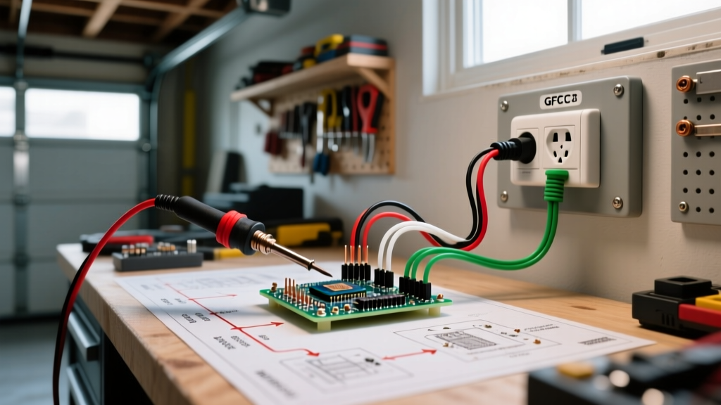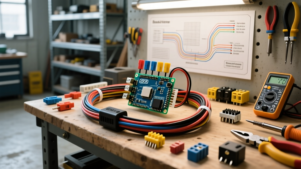

When towing a heavy travel trailer, car hauler, or equipment trailer, your braking system is the single most critical safety component on the road. A properly executed 7 pin electric trailer brake wiring with breakaway system ensures that your trailer stops in sync with your tow vehicle and, in the event of a catastrophic hitch failure, applies maximum braking force to prevent a runaway disaster. According to the Federal Motor Carrier Safety Administration (FMCSA) 49 CFR § 393.43, breakaway systems must be capable of holding the trailer in a stopped position and applying immediate emergency braking. Yet, countless DIY installations fail due to undersized wire, poor grounding, and incorrect breakaway switch routing.
This comprehensive material and tool guide cuts through the fluff. We will detail the exact components, wire gauges, and professional-grade tools required to build a robust, voltage-drop-resistant 7-way RV blade wiring harness with an integrated breakaway circuit for the 2026 towing season.
The Core Components: What You Actually Need
Do not rely on the pre-installed, undersized wiring that comes with budget trailers. Upgrading your harness with marine-grade and heavy-duty automotive components is the hallmark of a professional installation. Below is the definitive bill of materials for a tandem-axle trailer (4 electric brakes).
| Component | Recommended 2026 Model | Est. Price | Purpose & Spec |
|---|---|---|---|
| 7-Way RV Plug (Trailer Side) | Hopkins Endurance 48425 | $18 - $24 | Heavy-duty ABS housing, oversized copper pins for high amperage. |
| Breakaway Switch Kit | Tekonsha 2028 / Curt 51140 | $15 - $22 | Normally-open switch with 48-inch steel lanyard and 12V rated contacts. |
| Primary Harness Wire | Southwire 7-Conductor 12 AWG | $3.50 / ft | Jacketed multi-conductor cable for running from tongue to axles. | Heavy Ground & Brake Feed | Southwire 10 AWG Primary (White/Blue) | $0.90 / ft | Upgraded gauge to eliminate voltage drop on 25+ foot trailers. |
| Heat Shrink Tubing | Ancor Marine 422025 (Adhesive) | $12 - $18 | 3:1 shrink ratio with internal polyamide sealant for waterproof splices. |
| Dielectric Grease | Permatex 22058 | $8 - $12 | Prevents galvanic corrosion on the 7-pin connector face. |
Essential Tools for a Professional-Grade Installation
The right tools prevent stranded wires, cold solder joints, and melted insulation. Discard the cheap crimping pliers from your local hardware store.
- Wire Strippers & Crimpers: Knipex 95 62 200 or Klein Tools 11063W. You need clean cuts on 10 AWG and 12 AWG wire without nicking the copper strands.
- Soldering Station: Hakko FX-888D with a heavy chisel tip (T18-C4). Soldering 10 AWG wire requires high thermal mass; standard butane torch irons will scorch the insulation before the core melts the solder.
- Multimeter: Fluke 117 True-RMS. Essential for testing voltage drop across the 7-pin connector and verifying breakaway switch continuity.
- Heat Gun: Wagner HT1000. Required for properly shrinking the Ancor adhesive heat shrink to ensure a watertight seal.
Standard 7-Way RV Blade Pinout & Topology
Before cutting any wire, you must understand the SAE J286 / RVIA standard 7-way RV blade pinout. Miswiring the auxiliary and brake pins is a leading cause of blown fuses in modern tow vehicles. For a deeper dive into standard trailer wiring color codes, the etrailer.com Wiring FAQ and Technical Guide is an excellent visual resource.
- Pin 1 (Ground): White. Must be bolted directly to the trailer frame with a star washer. Pro-Tip: Run a dedicated 10 AWG white wire from Pin 1 all the way to the brake magnets.
- Pin 2 (Electric Brakes): Blue. Carries the PWM (Pulse Width Modulation) signal from the tow vehicle's brake controller. Use 12 AWG minimum, 10 AWG preferred.
- Pin 3 (Tail/Running Lights): Brown. 14 AWG is sufficient.
- Pin 4 (12V Auxiliary): Black. Charges the trailer battery or powers interior 12V appliances. Use 10 AWG to handle 30A+ charging currents.
- Pin 5 (Left Turn/Stop): Yellow. 14 AWG.
- Pin 6 (Right Turn/Stop): Green. 14 AWG.
- Pin 7 (Backup Lights/Aux): Red or Purple. 14 AWG.
Integrating the Breakaway Circuit: Step-by-Step
The breakaway system is your ultimate failsafe. When the trailer separates from the hitch, the steel lanyard pulls the pin from the switch, closing the circuit and sending 12V directly to the electric brakes. Here is how to wire it correctly.
Step 1: Mounting the Switch and Battery Connection
Mount the Tekonsha 2028 breakaway switch on the trailer tongue, positioned so the lanyard has a straight, unobstructed path to the tow vehicle's frame or bumper. Critical Rule: The power feed for the breakaway switch MUST come directly from the trailer's onboard 12V battery positive terminal. Do not wire it to the 7-pin's black auxiliary wire. If the trailer detaches, the 7-pin connection is severed, meaning the black wire is dead. The breakaway system requires the onboard battery to function.
Step 2: Splicing into the Brake Feed
The second wire from the breakaway switch must be spliced into the blue electric brake feed wire. Locate a point on the blue wire roughly 12 inches behind the 7-pin plug.
- Strip 1/2 inch of insulation from the blue brake wire and the breakaway switch wire.
- Twist the copper strands tightly and apply rosin-core solder using your Hakko station.
- Slide a piece of Ancor 3:1 adhesive heat shrink over the joint.
- Apply heat evenly until the shrink conforms tightly and a small bead of adhesive seals the edges.
Warning: The Grounding Bottleneck
Electric trailer brakes typically draw 3.5 to 4.5 amps each. A tandem-axle trailer pulls up to 18 amps during maximum braking. If your ground wire (white) is undersized or relies on a rusty frame connection, the voltage will drop, resulting in weak braking and overheated wires. Always run a dedicated 10 AWG ground wire from the 7-pin plug directly to a common ground bus near the axles, then branch out to the individual brake magnets with 12 AWG wire.
Advanced Troubleshooting & Edge Cases
Even with premium materials, environmental factors and long wire runs introduce electrical edge cases. Keep these troubleshooting frameworks in mind when testing your 7 pin electric trailer brake wiring with breakaway setup.
Voltage Drop on 30+ Foot Trailers
If you are wiring a 30-foot toy hauler, the distance from the 7-pin plug to the rear axle brake magnets can exceed 45 feet (round trip for power and ground). At 18 amps, 12 AWG wire will experience a voltage drop of nearly 1.5 volts, leaving your brake magnets with only 10.5V. This reduces braking torque by up to 20%. Solution: Run 10 AWG blue and white wires the entire length of the trailer, stepping down to 12 AWG only for the final 3-foot drop to the individual brake magnets.
Corrosion at the 7-Way Plug
The connection between the tow vehicle and trailer is highly susceptible to road salt and moisture. Galvanic corrosion between the brass pins and copper wire creates high resistance. Solution: After crimping and soldering the wires into the Hopkins 48425 plug, fill the rear cavity with a marine-grade potting compound or high-density silicone sealant. Coat the exposed brass pins with Permatex dielectric grease before every hookup.
Testing the Breakaway Switch
Do not test the breakaway system by simply pulling the pin while parked. Without the trailer moving, you cannot verify if the brakes are actually engaging with enough force to stop the rig. Solution: With the trailer hitched and the breakaway pin pulled, attempt to pull forward slowly in a safe, empty lot. The tow vehicle should feel immediate, heavy resistance, and the trailer brakes should lock or drag heavily. If the wheels turn freely, check the inline fuse on the trailer battery positive cable and verify continuity across the switch with your Fluke multimeter.
Final Thoughts on 2026 Towing Safety
Upgrading your 7 pin electric trailer brake wiring with breakaway components is an investment in safety and peace of mind. By utilizing 10 AWG ground and brake feeds, marine-grade adhesive heat shrink, and properly routing the breakaway switch to the onboard battery, you eliminate the most common failure points found in factory trailer wiring. Always verify your work with a True-RMS multimeter and adhere to FMCSA and local DOT regulations before hitting the highway.