
The 2026 Standard: Integrating Microcontroller Lighting into Home Remodels
As smart home technology evolves in 2026, off-the-shelf Wi-Fi bulbs are increasingly being replaced by custom, architectural-grade LED lighting systems. For DIYers and tech-savvy homeowners, arduino led wiring—often utilizing ESP32 microcontrollers running WLED firmware or Arduino Mega boards—has become the gold standard for controlling addressable LED strips (like WS2812B and APA102) and high-power COB LED arrays. However, the success of these custom lighting installations is rarely determined by the code you write; it is determined by the physical infrastructure you plan before the drywall goes up.
Treating 5V, 12V, and 24V DC low-voltage wiring with the same rigorous planning as 120V AC Romex is critical. This guide bridges the gap between microcontroller hobbyist knowledge and professional electrical rough-in planning, ensuring your renovation supports high-amperage, data-driven LED lighting without voltage drop, signal degradation, or code violations.
Bridging High-Voltage and Low-Voltage Code Requirements
When running low-voltage DC lines alongside standard AC household wiring, you must adhere to the National Electrical Code (NEC). The National Fire Protection Association (NFPA) NEC Guidelines outline specific separation requirements to prevent electromagnetic interference (EMI) and fire hazards.
NEC Article 411 & Article 725 Compliance: Lighting systems operating at 30 volts or less (Article 411) and Class 2 power-limited circuits (Article 725) must be separated from standard 120V/240V Class 1 power wires by at least 2 inches. If they must cross or run parallel in tight stud bays, the low-voltage wiring must be separated by a physical barrier, or you must use CL2/CL3-rated jacketed cable designed to withstand 600V AC fault conditions.
During your renovation rough-in, always dedicate specific stud bays or conduit runs exclusively for your DC power and data lines. Never share a standard 4x4 electrical junction box with both 120V AC wire nuts and 24V DC terminal blocks unless the box features a UL-listed physical divider.
Infrastructure Planning: Conduit, Chases, and Junction Boxes
The biggest mistake in Arduino LED renovation planning is hard-wiring DC lines directly through studs without a pull-string or conduit. LED technology changes rapidly; you will eventually want to upgrade from 12V single-color COB strips to 24V high-density addressable matrices.
The Smurf Tube Strategy
Install 1/2-inch or 3/4-inch Electrical Nonmetallic Tubing (ENT), commonly known as smurf tube, from your central controller location to every lighting zone.
- Cost Estimate: 100 feet of 1/2-inch ENT costs approximately $18-$22 in 2026.
- Pull Boxes: Install blank-cover junction boxes at every 90-degree bend or every 20 feet of straight run to facilitate future wire pulling.
- Access Panels: Never bury your Arduino enclosures or power supplies behind sealed drywall. Frame out 12x12 inch or 16x16 inch access panels in closets, above cabinets, or in basement drop-ceilings where your central hardware will live.
Calculating Voltage Drop for Long LED Runs
Voltage drop is the silent killer of Arduino LED projects. Addressable LEDs like the WS2812B draw massive current spikes when displaying full white (up to 60mA per LED). A 5-meter strip of 60-LED/m WS2812B can pull 18 Amps at 5V. If your wire gauge is too thin, the LEDs at the end of the run will starve for voltage, resulting in a yellow/pink tint or severe flickering.
Consult the Adafruit NeoPixel Uberguide for baseline power injection rules, and use the table below to plan your wire gauge during the rough-in phase based on your chosen strip voltage and run length.
| Strip Type (60 LED/m) | Voltage | Max Current | 5m Run (AWG) | 10m Run (AWG) | 15m Run (AWG) |
|---|---|---|---|---|---|
| WS2812B (Standard) | 5V | 18.0A | 14 AWG | 10 AWG | 8 AWG (Inject Power) |
| COB RGB (Diffused) | 12V | 7.5A | 18 AWG | 14 AWG | 12 AWG |
| High-Density Addressable | 24V | 4.2A | 20 AWG | 16 AWG | 14 AWG |
Pro-Tip for Renovators: Always pull stranded copper wire rather than solid core for low-voltage DC runs. Stranded wire (like automotive primary wire or CL2-rated speaker wire) handles the heat dissipation of high-amperage DC loads more effectively and is easier to pull through ENT conduit.
Power Supply and Controller Placement Strategy
Your Arduino or ESP32-S3 microcontroller requires a stable 5V logic supply, while your LED strips will likely require 12V or 24V. During the renovation planning phase, you must designate a well-ventilated, dry area for your power supplies.
Selecting the Right Power Supply
Avoid cheap, unbranded Amazon power supplies that lack active Power Factor Correction (PFC) or proper thermal shutoffs. For architectural remodels, specify Mean Well LRS or HLG series power supplies. A Mean Well LRS-350-24 (24V, 14.6A) costs around $45-$55 and features a built-in metal mesh casing that acts as a heatsink and grounding point.
Logic Level Shifting
According to the Arduino Official Documentation and ESP32 hardware specs, microcontrollers output data signals at 3.3V. However, 5V addressable LEDs require a 5V data signal to register reliably over long wire runs. Plan space in your central enclosure for a 74AHCT125 level shifter IC to boost the 3.3V data signal to 5V, preventing data corruption and random LED flickering.
Step-by-Step Rough-In Checklist for Electricians and DIYers
- Map the Lighting Zones: Draw a floor plan identifying every LED run. Calculate the maximum wattage for each zone to determine PSU sizing (always add a 20% overhead safety margin).
- Install ENT Conduit: Run 1/2-inch smurf tube from the central AV/Smart Home closet to the ceiling coves, under-cabinet tracks, and stair tread channels.
- Pull the Wire: Pull CL2-rated stranded wire. Always pull two extra ground wires alongside your main power and data lines to create a dedicated signal ground, preventing ground loops.
- Install Data Termination Points: At the end of long APA102 (SPI) data runs, plan for a 10k-ohm pull-up resistor on the clock and data lines to prevent signal reflection.
- Frame Access Panels: Ensure all PSU and Arduino Mega/ESP32 enclosures are accessible. Metal enclosures (NEMA 1) should be mounted to studs with adequate clearance for airflow.
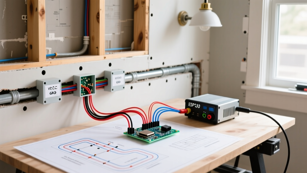
- Test Before Drywall: Use a multimeter to check continuity and ensure no staples or screws have pierced the low-voltage wiring before the insulation and drywall crews arrive.
Common Failure Modes in Retrofit Arduino LED Wiring
Even with perfect code, physical wiring flaws will ruin a smart lighting installation. Watch out for these specific failure modes:
- Ground Loops and Flickering: If your Arduino is powered by a USB wall wart, but the LED strip is powered by a separate 24V Mean Well PSU, the differing ground potentials will cause data errors. Solution: Wire the DC ground (V-) of the LED power supply directly to the Arduino's GND pin using a thick (18 AWG) wire.
Data Signal Degradation over CAT5: Many DIYers attempt to use leftover CAT5 ethernet cable for WS2812B data lines. While it works for short distances, the capacitance of twisted pairs degrades the high-frequency square wave of the data signal past 15 feet. Solution: Use unshielded, untwisted 18 AWG stranded wire for single-wire data protocols, or switch to APA102 (DotStar) LEDs which use a dedicated Clock and Data line (SPI) that is far more resistant to capacitance and EMI. - Thermal Throttling in Enclosures: Mean Well power supplies operating at 80% load or higher will get hot. If you seal them inside a wall cavity filled with fiberglass insulation, they will thermally shut off. Solution: Mount PSUs inside vented metal project boxes with a small 12V PC fan wired to a thermal switch.
Conclusion
Planning your Arduino LED wiring infrastructure during the demolition and framing stages of a renovation saves thousands of dollars in retrofitting costs. By respecting NEC low-voltage separation codes, calculating voltage drop accurately, and utilizing ENT conduit for future-proofing, you can build a custom, microcontroller-driven lighting system that is as robust and reliable as your home's standard electrical grid. Treat your 5V data lines and 24V power runs with professional respect, and your smart home will perform flawlessly for decades.