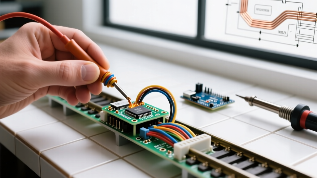

The Hidden Risks Beneath the Baseboard
When enthusiasts build a layout, the focus is often on scenery, rolling stock, and track geometry. However, the model railway electrics wiring hidden beneath the baseboard is the central nervous system of the entire operation. In 2026, with Digital Command Control (DCC) systems pushing 5 to 8 amps continuously across the rails, poor wiring practices are no longer just a nuisance that causes trains to stall—they are a legitimate fire hazard and a primary cause of expensive decoder and booster failures.
Inspecting your layout's electrical infrastructure for compliance with industry standards is critical. This guide details how to audit your wiring against the National Model Railroad Association (NMRA) Standards and Recommended Practices, ensure compliance with low-voltage electrical safety codes, and implement rigorous testing protocols to guarantee long-term reliability.
Understanding NMRA DCC Compliance Standards
The NMRA establishes the baseline for interoperability and safety in model railroading. For DCC systems, NMRA S-9.1 (Electrical Standards for Digital Command Control) and S-9.2 (DCC Communications Protocol) are the governing documents. While these standards primarily dictate the digital signal shape and packet structure, they implicitly demand a wiring infrastructure capable of delivering a clean, undistorted square wave to the locomotive.
Signal Degradation and Feeder Spacing
A common compliance failure during layout inspections is inadequate feeder wire density. DCC signals are high-frequency square waves (containing harmonics well into the MHz range). When these signals travel through long, un-fed sections of nickel-silver rail, the inherent resistance and inductance of the rail cause the square wave to 'ring' and degrade into a sine wave. If the voltage drop at the far end of a block falls below the NMRA-specified threshold (typically 11.5V minimum for HO scale), decoders will misinterpret bits, leading to erratic locomotive behavior or sudden stops.
Expert Insight: Never rely on rail joiners for electrical continuity. Thermal expansion and contraction in your layout room will cause metal joiners to loosen over time. Every single piece of flex track must have its own dedicated feeder wire soldered directly to the rail web.
Wire Gauge Audits and Voltage Drop Calculations
During an electrical inspection, verifying the American Wire Gauge (AWG) of your bus and feeder wires is the first physical check. Undersized bus wires act as resistors, generating heat and starving the track of current during a short-circuit event, which can prevent your circuit breakers from tripping.
| Scale | Main Bus AWG | Max Run Length (One Way) | Feeder Wire AWG | Max Feeder Length |
|---|---|---|---|---|
| N / TT | 14 AWG | 30 feet | 24 AWG | 12 inches |
| HO / OO | 14 AWG (12 AWG for >40ft) | 40 feet | 22 AWG | 12 inches |
| O / G | 12 AWG or 10 AWG | 50 feet | 20 AWG | 18 inches |
Note: 14 AWG stranded copper bus wire costs approximately $0.18 per foot in 2026. Do not compromise on this material cost to save a few dollars; the voltage drop penalty is severe.
Short Circuit Protection and 'The Quarter Test'
Compliance isn't just about the wire; it's about how the system reacts to a fault. NMRA guidelines and general electrical safety principles dictate that a short circuit must be cleared almost instantaneously to prevent track melting or fire. Modern DCC boosters have built-in short-circuit protection, but the internal breaker may require 3 to 5 amps to trip. If your wiring has high resistance, the current might never reach 5 amps, leaving the booster outputting maximum power into a dead short.
Performing the Quarter Test
To inspect your short-circuit compliance, perform the 'Quarter Test' at the absolute furthest electrical point from your booster on every power district.
- Place a standard copper/nickel coin (or a dedicated 0.1-ohm test resistor) across both rails to create a dead short.
- The booster or district circuit breaker must trip and shut off power within 100 milliseconds.
- If the booster does not trip, or if you hear a buzzing sound while the coin gets hot, your bus wire is too thin, your connections have too much resistance, or your district breaker trip current is set too high.
Inspecting Electronic Circuit Breakers
For large layouts, dividing the track into power districts using electronic circuit breakers is mandatory for compliance. When inspecting these devices, verify the trip current settings. For example, the NCE EB1 (retailing around $35) features configurable trip currents via jumper pins. Ensure the jumpers are set to match the output of your specific booster (e.g., 2.5A or 5A). If you are using the DCC Specialties PSX-AC (~$45), check that the CVs governing the trip current and short-circuit messaging are correctly programmed to your layout's DCC address.
Solder Joint Integrity and Thermal Failure Modes
Visual inspection of solder joints beneath the layout is a critical part of the audit. The most common failure mode in model railway electrics wiring is solder wicking. This occurs when excessive heat is applied during soldering, causing the molten solder to wick up the strands of the feeder wire beneath the insulation. This creates a rigid, brittle section of wire right at the rail joint. Over years of thermal cycling and layout vibration, this brittle section will snap, causing an intermittent open circuit that is notoriously difficult to diagnose.
Inspection Checklist for Solder Joints
- Visual Check: The solder joint at the rail web should be shiny and smooth (a 'fillet'). Dull or grainy joints indicate a 'cold solder' joint, which introduces high electrical resistance.
- Flex Test: Gently tug the feeder wire. If the wire is stiff immediately above the solder joint, wicking has occurred. Apply a small drop of flexible PVA glue or hot melt over the joint to provide mechanical strain relief.
- Temperature Audit: If you are doing rework, ensure your soldering station (e.g., Weller WE1010 or Hakko FX-888D) is set to 350°C (662°F) when using 60/40 rosin-core flux. Lead-free solder requires higher temperatures (approx. 380°C) and is generally discouraged for rail joiners due to poor wetting characteristics.
Mains Power, Transformers, and NEC Compliance
While the track carries low-voltage DCC power, the transformers and power supplies sitting on the floor or mounted under the layout are connected to 120V/240V mains power. According to the National Fire Protection Association (NFPA) National Electrical Code (NEC), specifically Article 725 regarding Class 1 and Class 2 remote-control and signaling circuits, power supplies must be appropriately rated and protected.
Power Supply Audit Points
Never use unbranded, uncertified 'wall wart' power supplies purchased from dubious online marketplaces. In the event of an internal capacitor failure, these non-compliant units can pass lethal mains voltage directly to the DCC booster and subsequently to the rails. During your inspection, verify that every power supply bears a valid UL (Underwriters Laboratories), CE, or ETL certification mark. Furthermore, ensure that the mains-side wiring utilizes a minimum of 14 AWG wire for runs up to 15 amps, and that all AC connections are housed in enclosed, fire-retardant junction boxes rather than being spliced with exposed wire nuts under the layout.
Advanced Signal Diagnostics with the RRamp-TR
For the ultimate compliance verification, visual inspections must be paired with empirical data. The RRamp-TR DCC Ammeter/Voltmeter (priced around $120) is an indispensable tool for layout inspectors. Unlike a standard multimeter which will average out a DCC square wave and give a meaningless reading, the RRamp-TR is designed to read the true RMS voltage and current of a DCC signal.
Place the RRamp-TR at the end of your longest track run. Under no-load conditions, the voltage should read within 0.2V of the booster's output. Next, run a heavy sound-equipped locomotive (drawing approx. 0.75A to 1A) through the block. If the voltage drops by more than 0.5V under load, your bus wire is inadequate, or your feeder spacing is too wide. This empirical data is the gold standard for proving your model railway electrics wiring meets professional operational benchmarks.
Finalizing the Layout Audit
Inspecting model railway electrics wiring is not a one-time task; it should be an annual maintenance procedure. By adhering to NMRA signal standards, enforcing strict wire gauge limits, validating short-circuit trip times with the Quarter Test, and ensuring mains power supplies meet NFPA/NEC safety codes, you protect your financial investment and, more importantly, your home. A compliant layout is a reliable layout, ensuring that your trains run smoothly for decades without the risk of electrical failure or fire.