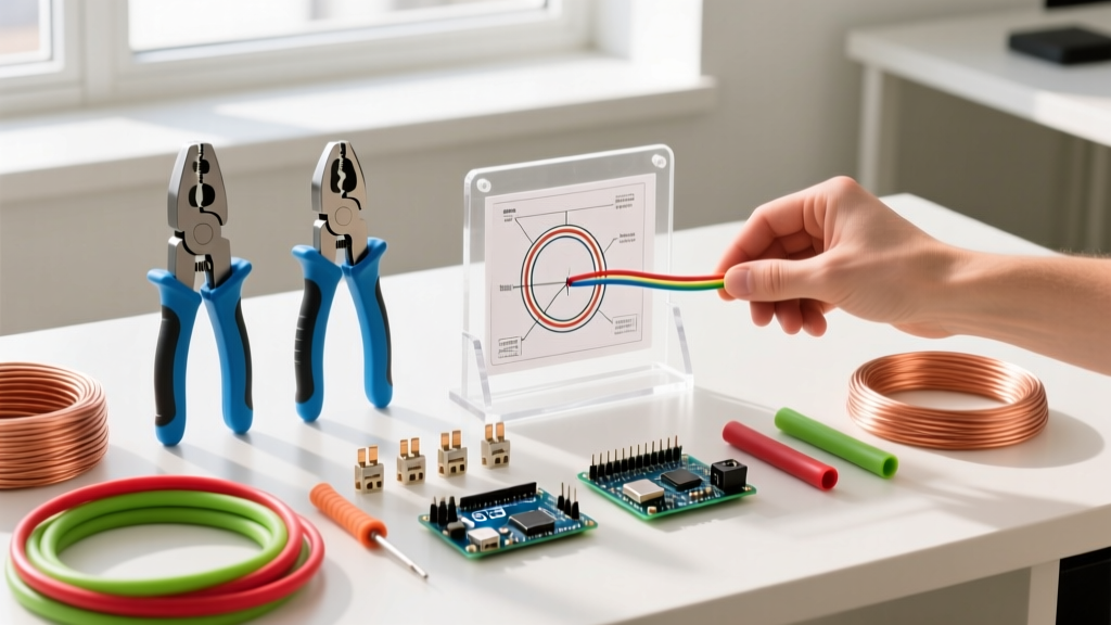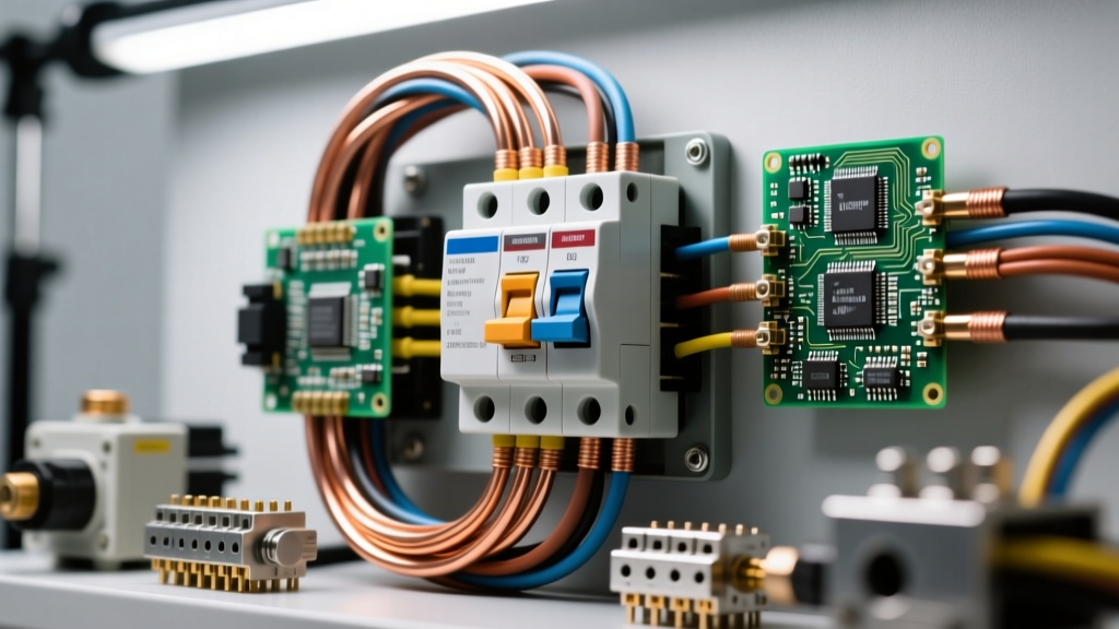

The Reality of Post-Install Faults in Modern Rewiring
Executing comprehensive electrical wiring upgrades in older homes or commercial spaces is rarely a simple plug-and-play endeavor. When you replace a legacy 100-amp Zinsco or Federal Pacific panel with a modern 200-amp Square D Homeline or Eaton BR series, or when you pull new 12 AWG copper to replace degraded cloth-sheathed wiring, you are introducing modern protection technologies to legacy infrastructure. This collision of old and new frequently results in post-installation gremlins: nuisance tripping, localized voltage drops, and thermal anomalies at termination points.
As a master electrician or an advanced DIYer, understanding the failure modes unique to electrical wiring upgrades is critical. This troubleshooting guide bypasses basic continuity checks and dives deep into the specific edge cases, code-mandated torque specifications, and circuit topology errors that cause upgraded systems to fail under load.
AFCI Nuisance Tripping and the Shared Neutral Epidemic
The most frequent complaint following electrical wiring upgrades in homes built between 1965 and 1985 is the immediate, unresettable tripping of new Combination-Type Arc Fault Circuit Interrupter (AFCI) breakers. Modern National Electrical Code (NEC) requirements mandate AFCI protection for nearly all 15A and 20A branch circuits. However, older homes heavily utilized Multi-Wire Branch Circuits (MWBCs)—a setup where two hot wires (on opposite phases) share a single neutral conductor to save copper.
Diagnosing the MWBC Conflict
Standard single-pole AFCI breakers (like the Square D HOM115CAFI or Eaton BR215AFC) monitor the current differential between the hot and the neutral. If an MWBC is connected to two separate single-pole AFCI breakers, the return current on the shared neutral will not match the current on either individual hot wire, causing the breaker's internal logic to interpret this as a parallel arc fault or ground fault, resulting in an immediate trip.
- The Fluke 87V Test: Set your multimeter to AC Voltage. Measure between the two hot conductors at the receptacle. If you read ~240V, they are on opposite legs and share a neutral. If you read 0V, they are on the same leg (a dangerous code violation that overheats the neutral).
- The Fix: You must replace the two single-pole breakers with a single 2-pole AFCI breaker (e.g., Square D HOM215CAFI) designed to monitor the vector sum of both hot legs and the shared neutral simultaneously. Alternatively, pull a dedicated 12/2 or 14/2 NM-B cable for each circuit to eliminate the shared neutral entirely.
Voltage Drop on Extended 20A Appliance Circuits
When performing electrical wiring upgrades for modern kitchens or home workshops, it is standard practice to install 20-amp circuits using 12 AWG copper wire. However, a hidden failure mode occurs when the physical run from the panel to the furthest receptacle exceeds 75 feet. Under a heavy continuous load (e.g., a 1500W space heater drawing 12.5A alongside a refrigerator compressor), the resistance of 12 AWG copper over long distances causes the voltage at the receptacle to drop below 114V (a >3% drop on a 120V nominal system).
Calculating and Correcting Long-Run Drop
Voltage drop can prematurely kill appliance compressors and cause LED drivers to flicker. If your upgrade involves runs exceeding 85 feet on a 20A circuit:
- Step up to 10 AWG THHN/THWN-2: Pulling 10 AWG wire through 1/2-inch EMT conduit reduces the resistance, keeping the voltage drop under the NEC recommended 3% threshold.
- Verify Breaker Terminals: Most standard 20A breakers are rated to accept up to #10 AWG wire. If your breaker only accepts #12 AWG, you must pigtail the 10 AWG wire to a short 12 AWG jumper using a properly torqued wire nut or WAGO 221 lever connector inside the panel gutter.
Troubleshooting Diagnostic Matrix
Use this rapid-reference matrix to isolate faults immediately following an upgrade.
| Symptom | Likely Root Cause | Diagnostic Tool / Test | Corrective Action |
|---|---|---|---|
| AFCI trips instantly upon load | Shared neutral (MWBC) on single-pole AFCI | Multimeter (Hot-to-Hot voltage test) | Install 2-pole AFCI or run dedicated neutrals |
| Subpanel neutral bar is energized | Neutral and ground bonded in subpanel | Non-contact voltage tester on neutral bar | Remove green bonding screw; isolate neutral bar |
| Receptacle reads 108V under load | Voltage drop on long 12 AWG run | True-RMS Multimeter under 15A load | Upsize conductors to 10 AWG or 8 AWG |
| Faint burning smell at panel | Loose termination causing arcing/heat | Infrared thermometer (Fluke 62 MAX+) | Re-torque lugs to manufacturer spec (in-lbs) |
Subpanel Grounding and Neutral Bonding Chaos
A catastrophic mistake frequently made during electrical wiring upgrades involving detached garages or basement finishing is the improper bonding of the neutral and ground bars in a subpanel. In your main service panel, the neutral and ground are bonded together, and the grounding electrode conductor connects to the earth. In a subpanel, the neutral and ground must remain strictly isolated.
The Floating Neutral Hazard
If the green bonding screw or bonding strap is left in place on a subpanel's neutral bar, normal neutral return current will flow back to the main panel via both the neutral wire and the bare copper grounding wire. This energizes the grounding system, meaning the metal casing of your washing machine, the conduit, and the subpanel enclosure could carry lethal current if the neutral wire ever severs.
- Troubleshooting Step: Turn off the main breaker. Remove the subpanel cover. Verify that the neutral bar is physically floating (mounted on insulators) and that the ground bar is bolted directly to the metal enclosure.
- Code Reference: NEC Article 250.142 strictly prohibits the use of the grounded (neutral) conductor for grounding equipment on the load side of the service disconnecting means.
Aluminum to Copper Pigtail Torque Failures
Many electrical wiring upgrades in homes built from 1965 to 1973 involve remediating single-strand aluminum branch wiring. While complete rewiring with copper is ideal, the Consumer Product Safety Commission (CPSC) recognizes the use of COPALUM crimps or AlumiConn lug connectors as safe, permanent repairs when executed correctly.
The most common failure mode here is not the connector itself, but the failure to use a calibrated torque screwdriver. Aluminum expands and contracts at a different thermal rate than copper and the brass/steel set screws. If an installer 'hand-tightens' an AlumiConn 95120 connector, the thermal cycling over six months will loosen the connection, leading to high-resistance arcing and fire.
CRITICAL CODE REQUIREMENT: Since the 2017 NEC cycle, NFPA 70 (NEC) Section 110.14(D) mandates that any termination marked with a torque value must be tightened using a calibrated torque tool. Hand-tightening is no longer a legal or safe practice for upgraded panels and lug connectors.
Exact Torque Specifications for Upgrades
When upgrading aluminum circuits using AlumiConn lugs, you must strip the aluminum wire, apply Noalox antioxidant paste to inhibit oxidation, and torque the set screws to exactly 20 inch-pounds. For main panel neutral and ground lugs, torque values typically range from 35 to 45 inch-pounds depending on the manufacturer (always check the sticker inside the panel deadfront). Invest in a specialized electrical torque screwdriver, such as the CDI 401SM or the Klein Tools 69065, to ensure every upgraded termination meets spec.
Final Verification and Thermal Imaging
Never consider an electrical wiring upgrade complete the moment the breakers are turned on. The true test occurs 24 to 48 hours later, after the circuits have undergone multiple thermal cycles under normal household loads. As recommended by safety advocates like the Electrical Safety Foundation International (ESFI), professional electricians should perform a post-install thermal scan.
Using an infrared camera or a spot thermometer, scan the panel deadfront (with covers removed and safe boundaries established) while heavy loads (HVAC, electric oven, dryers) are running. Any breaker or lug termination showing a temperature delta of more than 15°F above ambient room temperature indicates a high-resistance connection that must be de-energized and re-torqued immediately. By combining rigorous multimeter diagnostics with strict adherence to torque specifications, you ensure your wiring upgrades are not just code-compliant on paper, but bulletproof in reality.