
Beyond the Breadboard: Professional Button Wiring for Arduino
Transitioning a microcontroller project from a temporary breadboard prototype to a permanent, real-world enclosure requires a fundamental shift in how you approach physical connections. When tackling button wiring Arduino projects, the software logic is only half the battle; the physical hardware dictates the long-term reliability of your system. A poorly crimped wire or an under-specced tactile switch will lead to intermittent faults, switch bounce, and eventual mechanical failure.
As of 2026, the maker and industrial prototyping markets offer a vast array of components, but selecting the right materials requires understanding electrical tolerances, mechanical actuation limits, and proper termination techniques. This guide serves as your definitive material and tool reference for wiring physical buttons, toggles, and switches to Arduino-compatible microcontrollers (such as the Uno R4, Mega 2560, or ESP32 dev boards) for custom control panels, arcade cabinets, and industrial IoT interfaces.
Selecting the Right Switch: Tactile vs. Mechanical vs. Industrial
The switch is the primary user interface in any button-driven circuit. Choosing the wrong switch type for your specific environment is the most common point of failure in DIY electronics. According to the Adafruit Guide to Switches, understanding the mechanical lifecycle and actuation force is critical before cutting a single wire.
Tactile Switches (PCB & Panel Mount)
For internal PCB mounting or low-profile panel applications, the C&K PTS645 series remains the industry standard. These 6x6mm tactile switches offer a crisp mechanical feel and are rated for roughly 100,000 actuations. They are inexpensive (typically $0.10 to $0.15 each in bulk) but are not sealed against moisture, making them unsuitable for outdoor or wet environments without an external silicone boot.
Mechanical Keyboard Switches
For high-end consumer projects like custom macro pads or arcade controllers, Cherry MX or Gateron mechanical switches are superior. The Cherry MX1A-11NW (MX Red) provides a linear, 45cN actuation force and is rated for over 100 million keystrokes. Wiring these requires careful attention to their PCB-mount pins, usually necessitating a custom daughterboard or precise point-to-point soldering with 24 AWG wire.
Industrial Panel Mount Pushbuttons
If your Arduino is deployed in a garage, workshop, or factory floor, you must use industrial-rated hardware. The EAO Series 45 or standard 22mm momentary pushbuttons (often branded by Schneider Electric or Siemens) feature IP67 water resistance, heavy-duty screw-terminal or solder-lug terminations, and robust metal housings. Expect to pay between $12.00 and $25.00 per unit, but the reliability in harsh environments is unmatched.
| Switch Type | Recommended Model | Actuation Force | Lifecycle Rating | Best Use Case | Est. Price (2026) |
|---|---|---|---|---|---|
| Tactile (6x6mm) | C&K PTS645 | 130g - 260g | 100,000 cycles | Internal PCBs, light panels | $0.12 |
| Mechanical | Cherry MX Red | 45cN (Linear) | 100,000,000 cycles | Macro pads, gaming, high-use | $0.45 |
| Industrial 22mm | EAO Series 45 | ~400g (Heavy) | 1,000,000+ cycles | Workshops, outdoor, heavy machinery | $18.50 |
Wire Selection: Gauge, Jacket Material, and Length Limits
Wiring a button to a digital input pin seems trivial, but wire selection impacts signal integrity, especially over longer distances. Microcontroller digital input pins are high-impedance, meaning they draw almost zero current but are highly susceptible to electromagnetic interference (EMI) and capacitive coupling.
Optimal Wire Gauge and Material
For 99% of Arduino button wiring projects, 24 AWG or 22 AWG stranded silicone wire is the ideal choice. Silicone jackets offer extreme flexibility, high heat resistance (up to 200°C), and do not melt when soldered near the termination point. Avoid cheap PVC-jacketted ribbon cables for moving parts (like hinge-mounted buttons), as the copper strands will eventually fatigue and snap inside the stiff PVC insulation.
The Long-Distance Voltage Drop and Capacitance Problem
A common mistake is running a simple 5V digital signal over 10+ meters of wire to a remote button. The parasitic capacitance of long wire runs acts as a low-pass filter, rounding off the sharp digital edges of the button press, which the Arduino may misinterpret as switch bounce or fail to register entirely.
Pro Tip: If your button is located more than 3 meters (10 feet) from the Arduino, do not run raw 5V logic. Instead, use a local opto-isolator or a dedicated RS-485 transceiver module at the button location to convert the signal to a differential pair, completely eliminating EMI and capacitance issues.
Connectors and Termination: Ditching Dupont for Reliability
Dupont jumper wires (the standard 2.54mm pitch black connectors) are designed for temporary breadboard use. Their internal metal contacts rely on a weak spring tension that loosens over time, leading to intermittent disconnects. For permanent installations, use crimped connectors.
- JST-XH (2.54mm pitch): The gold standard for internal PCB-to-switch connections. They feature a positive locking mechanism that prevents vibration-induced disconnects.
- Molex KK 254: Excellent for high-density pin headers on the Arduino side, offering superior contact wiping action compared to Dupont.
- Panel Mount Screw Terminals: For industrial 22mm switches, use ring or spade terminals crimped onto your 22 AWG wire to mate with the switch's screw terminals. This allows for easy maintenance and swapping of switches without desoldering.
Essential Wiring Tools for the Workbench
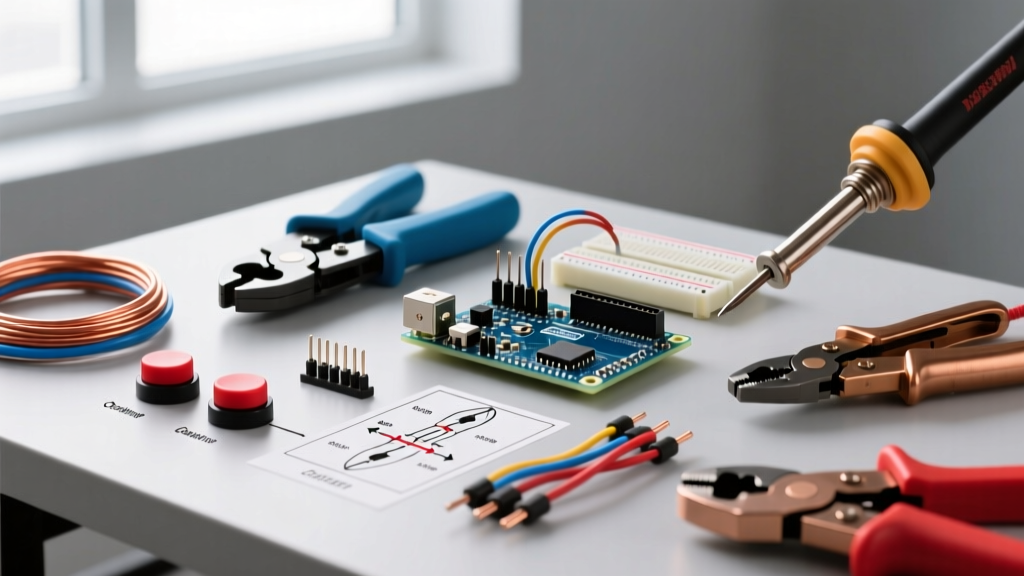
To achieve professional-grade terminations, you must invest in precision tools. A $3 hardware store crimping tool will ruin JST and Molex pins, causing them to crack or fail to grip the wire strands.
- Precision Wire Stripper: The Engineer PA-09 or Knipex 12 42 11. These allow you to cleanly strip 24 AWG silicone wire without nicking the fine copper strands, which drastically reduces the wire's tensile strength.
- Ratchet Crimper: The IWISS SN-28B (for JST and Molex KK series) or the IWISS SN-025 (for smaller Dupont-style pins). Ratchet crimpers ensure a uniform, gas-tight crimp every time by preventing the tool from opening until the exact pressure threshold is met.
- Flush Cutters: Hakko CHP-170. Essential for trimming zip ties, cutting component leads, and snipping excess wire flush against a solder joint.
- Digital Multimeter: A basic continuity tester (like the Klein Tools MM400) is mandatory for verifying your crimps and checking for short circuits before applying power to your Arduino.
Hardware Debouncing vs. Software Solutions
Mechanical switches do not make a clean electrical connection; the metal contacts physically bounce against each other for a few milliseconds before settling. According to the Arduino Digital Pins Documentation, this bounce can register as multiple rapid button presses in your code.
Software Debouncing
For most projects, handling bounce in software using the Bounce2 library or a simple millis() timer delay is the most cost-effective method, requiring no extra hardware.
Hardware Debouncing (RC Filters)
In environments with heavy electrical noise (like near AC motors or relays), software debouncing might not be enough. A hardware RC (Resistor-Capacitor) filter smooths the voltage spike. By placing a 10kΩ resistor in series with the switch and a 0.1µF ceramic capacitor between the Arduino input pin and ground, you create a low-pass filter that physically absorbs the micro-bounces. For a deep dive into the electrical theory, the SparkFun Pull-Up Resistor Tutorial provides excellent schematics for combining pull-up networks with debounce capacitors.
Internal vs. External Pull-Up Resistors
Modern Arduino boards (ATmega328P, ESP32) feature internal 20kΩ to 50kΩ pull-up resistors activated via pinMode(pin, INPUT_PULLUP). This eliminates the need to wire external resistors for 90% of basic projects. However, for long wire runs (over 2 meters), the internal pull-up is too weak to overcome the wire's capacitance and environmental noise. In these cases, wire an external 4.7kΩ or 10kΩ pull-down/pull-up resistor directly at the switch location to provide a stronger bias voltage.
Common Wiring Failure Modes and Troubleshooting
Even with the best materials, mistakes happen. Here is a diagnostic matrix for the most common physical wiring failures in Arduino button circuits:
- Phantom Presses (Ghosting): The Arduino registers a press when no button is pushed. Cause: Floating pins due to missing pull-up/pull-down resistors, or crosstalk from adjacent unshielded wires running parallel to AC mains. Fix: Enable
INPUT_PULLUPor route signal wires away from high-voltage lines. - Intermittent Connection: The button works only when the enclosure is perfectly still. Cause: Cold solder joints on the switch pins, or a non-ratcheting crimper failed to bite into the wire strands. Fix: Perform a pull-test on all crimps (they should withstand at least 5 lbs of force) and reflow suspect solder joints with fresh flux.
- Stuck 'High' or 'Low' State: The pin reads a constant state regardless of button presses. Cause: A short circuit between the signal wire and the 5V/GND rail, often caused by a stray strand of copper poking out of a poorly stripped wire end. Fix: Use a multimeter in continuity mode to trace the short from the Arduino header to the switch.
Summary Checklist for Your Next Build
Before finalizing your enclosure, ensure you have checked the following: verified switch lifecycle ratings for your expected usage, selected 24 AWG silicone wire for flexibility, utilized ratcheting crimpers for all JST/Molex terminations, and tested the physical wiring with a multimeter before uploading your final firmware. By treating your physical wiring with the same rigor as your software logic, your Arduino button interfaces will survive years of continuous operation in the real world.