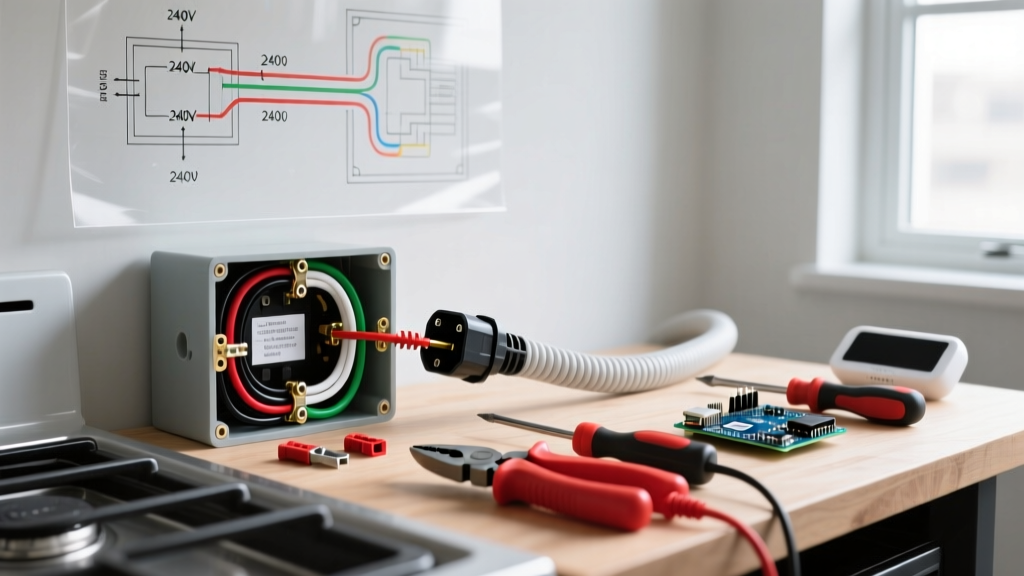

The 2026 Landscape of Electric Range Wiring
Modern electric ranges have evolved significantly from the simple resistive heating elements of the past. Today's smart appliances, such as the Samsung Bespoke and LG InstaView series, feature complex Electronic Oven Controls (EOCs), Wi-Fi modules, and induction cooktops that demand pristine electrical delivery. When troubleshooting wiring an electric range, you are no longer just dealing with high-amperage heating circuits; you are also managing sensitive 120V logic boards. A marginal connection that might have merely caused a flickering light on a 1990s model will instantly fry a $350 control board on a 2026 smart range. This guide provides a deep-dive diagnostic framework for identifying and resolving 240V and 120V connection faults at the receptacle, cord, and terminal block.
Mandatory Safety & Lockout/Tagout (LOTO)
CRITICAL WARNING: A 50-amp, 240-volt circuit possesses more than enough amperage to induce fatal ventricular fibrillation. Never troubleshoot live terminal blocks without Category III (CAT III) or Category IV (CAT IV) rated test leads and insulated tools. Always verify the absence of voltage before touching bare conductors.
Before removing the range's access panel, you must execute a proper Lockout/Tagout (LOTO) procedure. Locate the 50A double-pole breaker in your main service panel (typically a Square D HOM250 or Eaton BR250). Switch it to the OFF position and apply a physical padlock or breaker lockout device. According to the Occupational Safety and Health Administration (OSHA), verifying the absence of voltage with a properly functioning meter is the only acceptable way to confirm a zero-energy state.
Diagnostic Toolkit for 240V Circuits
To accurately troubleshoot wiring an electric range, standard cheap multimeters are insufficient and potentially dangerous. Assemble the following professional-grade toolkit:
- True-RMS Digital Multimeter (CAT III 600V minimum): The Fluke 117 ($180) or Klein Tools MM700 ($75) provides accurate readings even on non-linear loads generated by modern inverter boards.
- Non-Contact Voltage Tester (NCVT): Klein Tools NCVT-3 ($35) for initial proximity checks before making direct metal-to-metal contact.
- Insulated Screwdrivers: Wiha 1000V-rated insulated nut drivers and screwdrivers (approx. $45) to prevent accidental shorting between the L1/L2 terminals and the chassis ground.
- Infrared Thermometer or Thermal Camera: FLIR C5 ($450) or a basic Etekcity Lasergrip 774 ($25) to scan for hot spots at the breaker and terminal block under load.
The 4-Prong vs. 3-Prong Code Dilemma
One of the most frequent issues encountered when wiring an electric range in older homes is the mismatch between the appliance cord and the wall receptacle. The National Fire Protection Association (NFPA) updated the National Electrical Code (NEC) to mandate 4-prong receptacles (NEMA 14-50R) for all new installations. This separates the neutral (current-carrying) conductor from the ground (safety) conductor.
If you are retrofitting a new range into an older home with a 3-prong (NEMA 10-50R) receptacle, you must configure the range's terminal block bonding strap correctly. Failure to remove the bonding strap on a 4-prong cord, or failure to install it on a 3-prong cord, is the leading cause of chassis electrification and nuisance GFCI tripping.
Voltage Testing Matrix: Pinpointing the Fault
With the breaker ON and the range disconnected from the cord (testing the receptacle directly), use your True-RMS multimeter to probe the NEMA 14-50R receptacle. Compare your readings to the matrix below to isolate the fault.
| Test Point | Expected Reading | Fault Indication & Root Cause |
|---|---|---|
| L1 (Left Hot) to L2 (Right Hot) | 240V (±5%) | Reading < 220V: Utility transformer drop, undersized wire (e.g., 8 AWG instead of 6 AWG), or a failing double-pole breaker. |
| L1 to Neutral (Center) | 120V (±5%) | Reading 0V: Open neutral at the panel or receptacle. Reading 240V: Neutral is miswired to L2 at the panel. |
| L2 to Neutral (Center) | 120V (±5%) | Reading 0V: Open neutral. Reading 240V: Neutral is miswired to L1 at the panel. |
| Neutral to Ground (Bottom/U-Ground) | 0V to 2V | Reading > 5V: Shared neutral on the branch circuit, loose ground bus bar, or a bootleg ground at the receptacle. |
| L1 to Ground | 120V | Reading 0V: Missing equipment grounding conductor (EGC) or broken ground wire. |
Step-by-Step Terminal Block Troubleshooting
If the wall receptacle tests perfectly, the fault lies within the range's power cord or internal terminal block. Modern ranges use a 4-terminal block (L1, Neutral, L2, Ground). Follow this sequence:
- Inspect the Power Cord Strain Relief: Ensure the 3/4-inch strain relief connector is tightly secured to the range chassis. A loose strain relief allows the heavy 6 AWG cord to pull on the terminal block screws, causing arcing.
- Check for Thermal Damage: Look for blackened, melted, or deformed plastic around the terminal block. Leviton and GE terminal blocks (e.g., WB18X25161, approx. $22) are rated for high heat, but loose connections generate localized plasma arcs that will melt the phenolic resin.
- Verify the Bonding Strap: For a 4-prong cord, the green ground wire must attach to the chassis ground screw, and the white neutral must attach to the center silver terminal. The copper bonding strap connecting the center terminal to the chassis MUST be removed and tucked away.
- Torque the Connections: Hand-tightening is unacceptable. Use a torque screwdriver set to 45 in-lbs (inch-pounds) for the terminal block screws. Under-torquing causes high-resistance faults; over-torquing strips the brass threads.
Common Failure Mode 1: The Melted Terminal Block
Symptom: The range intermittently loses power, or the oven shuts off mid-cycle. A burning plastic smell is present.
Root Cause: A loose L1 or L2 connection at the terminal block. As current flows through a loose connection, resistance increases, generating extreme heat (I²R losses). This heat degrades the wire insulation and melts the block.
The Fix: Cut back the damaged wire to bare, clean copper. If the wire is too short, you must replace the entire pigtail. Install a new terminal block and torque to manufacturer specifications. Never attempt to salvage a heat-discolored terminal block.
Common Failure Mode 2: Electronic Oven Control (EOC) Failure
Symptom: The cooktop heating elements work perfectly (240V), but the digital display is dead, the oven won't heat, and the clock is blank (120V circuit failure).
Root Cause: An 'Open Neutral' condition. If the neutral wire disconnects at the receptacle or terminal block, the 120V control board attempts to pull its return current through the 240V heating elements in series. This sends a massive voltage spike through the low-voltage DC transformers on the EOC board, instantly vaporizing the internal varistors and fuses.
The Fix: According to data from the U.S. Consumer Product Safety Commission (CPSC), improper wiring leading to appliance fires and component destruction is a leading cause of electrical claims. You must replace the EOC board ($200-$450 depending on the model) and definitively repair the open neutral connection. Test the neutral continuity from the range plug to the main panel bus bar before applying power again.
Common Failure Mode 3: Phantom Tripping on AFCI/GFCI Breakers
Symptom: The 50A breaker trips immediately when the oven door opens or the interior light turns on.
Root Cause: In 2026, many local jurisdictions require AFCI/GFCI protection for kitchen appliance circuits. If the range's internal wiring harness has degraded insulation near the metal chassis, or if the 4-prong bonding strap was accidentally left in place, the GFCI sensor will detect current leaking to ground (or returning on the ground wire instead of the neutral) and trip the breaker.
The Fix: Remove the bonding strap if using a 4-prong cord. Inspect the internal door-switch wiring harness for pinched wires. If the breaker continues to trip, perform a megohmmeter (Megger) test on the branch circuit wiring to ensure the 6 AWG conductors inside the wall haven't suffered insulation breakdown.
Final Verification and Load Testing
Once all physical connections are verified, torqued, and the access panels are reinstalled, perform a live load test. Turn on all four surface burners to HIGH and set the oven to BAKE at 450°F. This forces the range to draw near its maximum amperage (typically 35-45 amps). Use your infrared thermometer to scan the breaker in the main panel and the receptacle faceplate. Temperatures should not exceed 40°C (104°F) above ambient room temperature. If the breaker face feels hot to the touch after 15 minutes, the breaker's internal bimetallic strip is fatigued, and the 50A breaker must be replaced immediately.
Troubleshooting wiring an electric range requires a methodical approach, prioritizing safety and code compliance over quick fixes. By utilizing precise voltage matrices, adhering to NEC grounding mandates, and respecting torque specifications, you ensure the longevity of modern smart appliances and the safety of the home's electrical infrastructure.