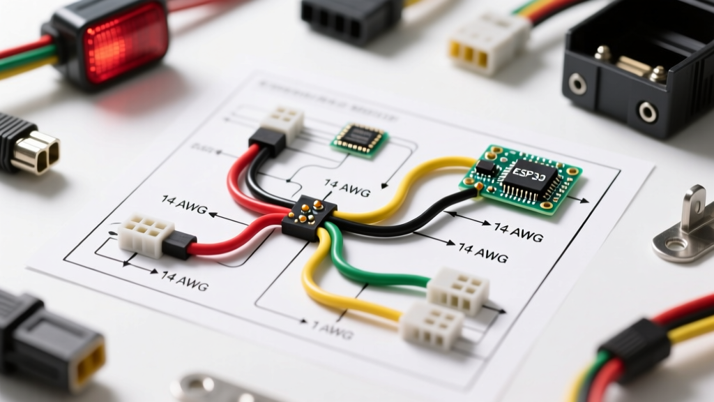

Beyond Color Matching: The Safety-First Approach to Trailer Lighting
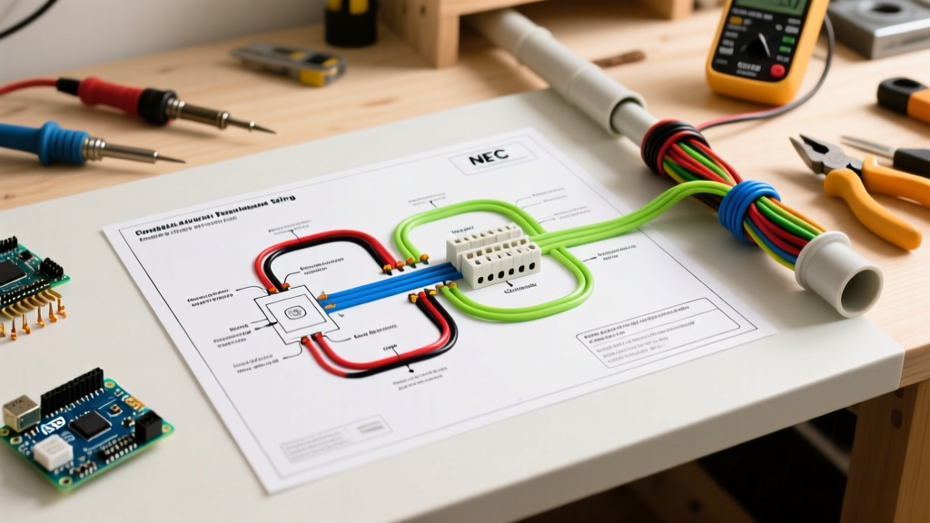
When most DIYers search for a wiring diagram for trailer tail lights, they are simply looking for a color-matching cheat sheet. While connecting the brown wire to the running lights and the green wire to the right turn signal will make the bulbs illuminate, it does not guarantee your trailer is legal or safe to tow on public roads. In the United States, trailer lighting is strictly governed by the Department of Transportation (DOT) and the National Highway Traffic Safety Administration (NHTSA). Failing to meet these standards doesn't just risk a hefty citation from highway patrol; it introduces severe liability in the event of a rear-end collision.
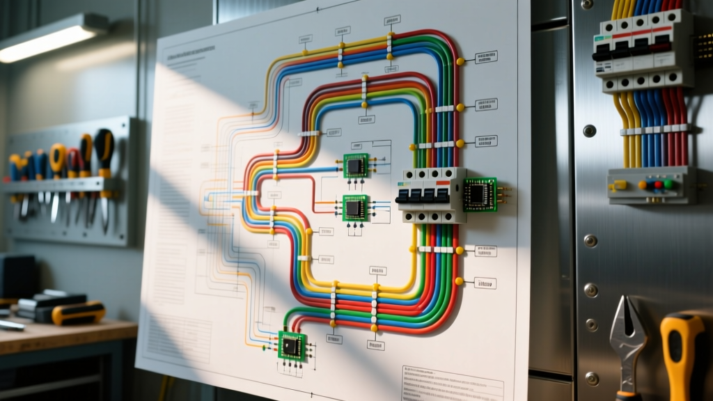
This guide transcends basic pinout charts. We will break down the exact wiring schematics for 4-way and 7-way connectors, cross-referenced with Federal Motor Vehicle Safety Standard (FMVSS) 108 requirements for lamp placement, wire gauge sizing to prevent voltage-induced failure modes, and heavy-duty waterproofing techniques that survive harsh highway environments.
Standard 4-Way Flat and 7-Way RV Blade Pinouts
The physical connection between your tow vehicle and the trailer dictates the circuit layout. The two most common configurations for utility, boat, and travel trailers are the 4-way flat and the 7-way RV blade connectors. Below are the standardized, code-compliant pin assignments.
4-Way Flat Connector (Trailers Under 80 Inches Wide)
| Pin Position | Wire Color | Circuit Function | Typical Amperage Draw (Incandescent) |
|---|---|---|---|
| Pin 1 (Exposed/Ground) | White | Chassis Ground Return | N/A (Carries combined return load) |
| Pin 2 (Left) | Yellow | Left Turn Signal & Brake | 4.2A (Two 21W bulbs) |
| Pin 3 (Center) | Green | Right Turn Signal & Brake | 4.2A (Two 21W bulbs) |
| Pin 4 (Right) | Brown | Tail Lights, Running Lights, License Plate | 6.0A+ (Multiple marker lamps) |
7-Way RV Blade Connector (Heavy Duty, Travel Trailers, Brakes)
| Pin Position (Clockwise) | Wire Color | Circuit Function |
|---|---|---|
| Center | White | Ground Return (Must be 10 AWG minimum) |
| Pin 1 (Top) | Black | 12V Auxiliary Power (Battery Charge) |
| Pin 2 (Top Right) | Brown | Tail Lights & Clearance Markers |
| Pin 3 (Bottom Right) | Green | Right Turn & Brake |
| Pin 4 (Bottom Center) | Yellow | Left Turn & Brake |
| Pin 5 (Bottom Left) | Blue | Electric Trailer Brake Controller Output |
| Pin 6 (Top Left) | Red / Purple | Reverse Lights / Auxiliary Rear Power |
FMVSS 108 & DOT Compliance: Placement and Intensity
Having the correct wiring diagram for trailer tail lights is only half the battle; the physical placement of the lamps is where most home-built and modified trailers fail DOT inspections. According to FMCSA Part 393 Subpart F and FMVSS 108, trailers over 80 inches wide require a specific suite of identification and clearance lamps.
- Tail Lamps (Rear Position): Must emit red light, mounted symmetrically as far apart as practicable, and at a height between 15 and 72 inches from the ground.
- Stop Lamps (Brake Lights): Must emit red light, mounted between 15 and 72 inches high. They must illuminate upon application of the tow vehicle's service brakes.
- Turn Signals: May be amber or red, mounted between 15 and 83 inches high.
- Identification (ID) Lamps: Trailers 80 inches or wider must have three red ID lamps mounted as close together as possible, centered on the rear vertical centerline, and placed as high as practicable (usually on the top rear crossmember).
Expert Insight: Many DIY builders mount tail lights on the bottom lip of a custom bumper for a clean look. If the center of the lens is below 15 inches from the pavement, the trailer is federally non-compliant and can be impounded during a commercial DOT weigh-station inspection.
Wire Gauge Selection and Voltage Drop Mitigation
Trailer wiring operates in a harsh 12V DC environment where voltage drop is the enemy of safety. If the wire gauge is too thin for the length of the run, the tail lights will dim, and the electric brake controller (on 7-way setups) will fail to deliver adequate amperage to the brake magnets. Automotive wire should meet SAE J1128 specifications (GXL or TXL insulation) rather than standard THHN building wire, as it resists vibration, oil, and extreme temperature cycling.
Minimum Wire Gauge Matrix by Trailer Length
| Trailer Length | Main Harness (7-Way) | Main Harness (4-Way) | Tail/Marker Branch Circuits | Turn/Brake Branch Circuits |
|---|---|---|---|---|
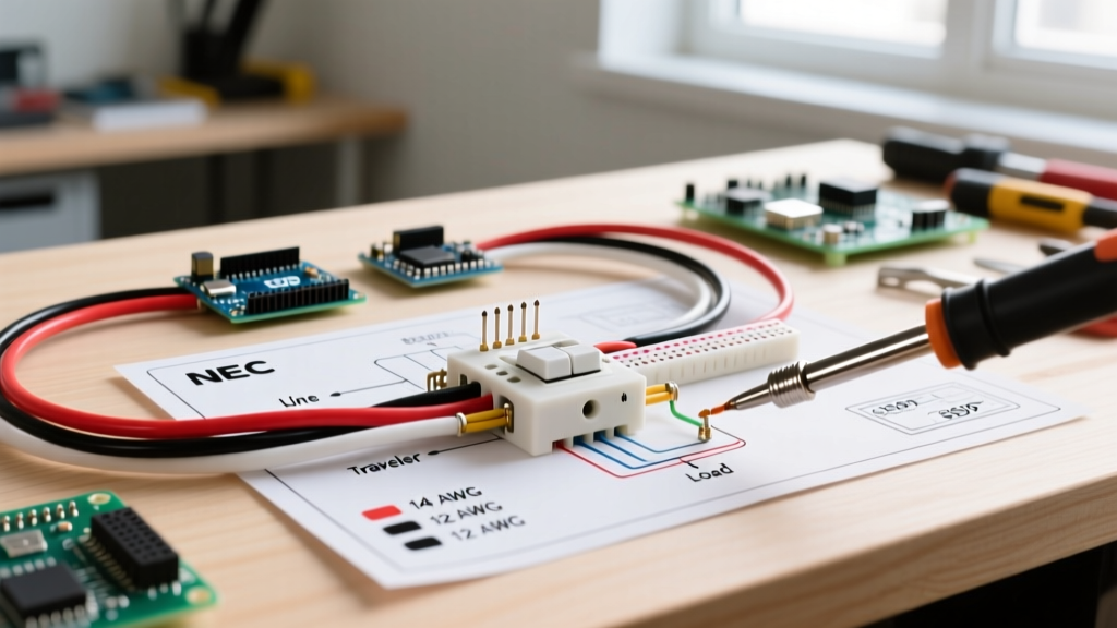
| Under 15 Feet | 10 AWG | 14 AWG | 16 AWG | 14 AWG |
| 15 to 25 Feet | 10 AWG | 12 AWG | 14 AWG | 12 AWG |
| 25 to 40+ Feet | 8 AWG | 10 AWG | 12 AWG | 10 AWG |
Note: Always size the white ground wire to match or exceed the largest positive supply wire in the harness. A bottleneck on the ground path causes erratic lighting behavior and overheated connectors.
The Grounding Fallacy: Chassis vs. Dedicated Return Paths
The single most common failure mode in trailer lighting is a bad ground. Traditional wiring diagrams often show the white wire attached to the trailer's steel frame, relying on the chassis to return current to the tow vehicle. In 2026, with the widespread use of aluminum-frame trailers, composite beds, and heavy powder-coating, chassis grounding is a massive liability.
The Code-Compliant Solution: Run a dedicated white ground wire all the way back to every single lamp housing. Do not rely on the metal mounting screws of the light fixture to ground the circuit to the frame. Use a ring terminal (12-10 AWG) attached directly to the lamp's ground lead, and run it back to the main harness. If you must bond to the chassis, use a self-tapping grounding screw with a star washer to bite through paint and rust, and coat the connection in dielectric grease.
Waterproofing and Environmental Hardening
Trailer wiring is constantly subjected to hydrostatic pressure from rain, road spray, and occasional submersion (in the case of boat trailers). Standard vinyl electrical tape will unwrap and fail within a single season. To ensure long-term reliability and prevent short circuits that could blow the tow vehicle's BCM (Body Control Module) fuses, follow these hardening steps:
- Adhesive-Lined Heat Shrink: Use dual-wall, adhesive-lined polyolefin heat shrink (e.g., 3M FP-301 or Molex equivalents). When heated to 120°C, the inner thermoplastic layer melts and seals the wire strands, completely blocking moisture ingress.
- Dielectric Grease: Apply a silicone-based dielectric grease (such as Permatex 22058) to all 4-way and 7-way plug terminals. This prevents galvanic corrosion between dissimilar metals (like brass pins and copper wires).
- Loom and Clipping: Route all wiring through split corrugated loom tubing, securing it with UV-resistant nylon zip ties or aluminum P-clips every 18 inches to prevent chafing against the frame.
LED Upgrades: Hyperflashing and CANbus Edge Cases
Upgrading from incandescent bulbs to LED trailer lights (such as the Optronics STL78RB series) is highly recommended for safety due to their faster illumination time and lower amperage draw. However, this creates a specific electrical edge case.
Because LEDs draw a fraction of the amperage of halogen bulbs, the tow vehicle's flasher relay or CANbus system may interpret the low draw as a 'blown bulb.' This results in hyperflashing (turn signals blinking twice as fast) or the tow vehicle's dashboard throwing a bulb-out warning.
The Fix: Do not simply splice in cheap ceramic load resistors, which generate immense heat and pose a fire risk to trailer wiring. Instead, install a dedicated smart converter module (like the Curt 56382 or Tekonsha 119190KIT) at the tow vehicle's harness. These modules use solid-state relays to isolate the trailer's LED draw from the tow vehicle's sensitive multiplexed lighting circuits, ensuring DOT-compliant flash rates without overheating the wiring.
Summary Checklist for a Safe, Legal Trailer Harness
- Verify tail lamp mounting height is strictly between 15 and 72 inches.
- Use SAE J1128 GXL/TXL wire, sized for the total length of the trailer.
- Run dedicated ground wires to all lamps; avoid relying solely on the chassis.
- Seal all splices with adhesive-lined heat shrink, never vinyl tape.
- Use solid-state converters for LED upgrades to prevent CANbus faults and hyperflashing.