
The Engineering Behind Classic GM Push-Button Conversions
Converting a classic muscle car or hot rod from a traditional keyed steering column to a modern wiring diagram for push button start setup is one of the most rewarding electrical upgrades a DIY builder can tackle. Whether you are eliminating a worn-out GM steering column switch, building a dedicated track car, or integrating a hidden anti-theft kill switch, moving to a dash-mounted momentary button requires a precise understanding of 12V automotive relay logic.
Unlike modern vehicles with complex CAN-bus networks and immobilizers, classic General Motors (GM) vehicles from the 1960s through the 1980s utilize a straightforward, high-amperage starter solenoid system. However, a common pitfall in aftermarket conversions is ignoring the factory ballast resistor bypass circuit. If wired incorrectly, your engine will crank perfectly on the button press, but die the exact millisecond you release it. This guide provides a comprehensive, vehicle-specific blueprint to execute this conversion flawlessly in 2026, utilizing modern marine-grade components and SAE-compliant wiring standards.
2026 Bill of Materials (BOM) & Component Specs
With copper prices stabilizing in early 2026, high-quality TXL (Thermoplastic Cross-Linked) wire remains an affordable necessity for engine bay routing due to its 125°C temperature rating and thin-wall insulation. Below is the exact BOM required for a safe, reliable GM push-button conversion.
| Component | Specification / Model Number | Est. 2026 Cost | Function in Circuit |
|---|---|---|---|
| Momentary Push Button | IP67-Rated, 16A/12VDC, Normally Open (NO) | $18.50 | User interface; completes control circuit |
| Starter Relay | Bosch-Style ISO Mini (30A/40A), 5-Pin | $9.00 | Isolates high-amperage starter draw from dash wiring |
| Anti-Grind Relay | Painless Performance 30812 or equivalent | $24.99 | Prevents starter engagement while engine is running |
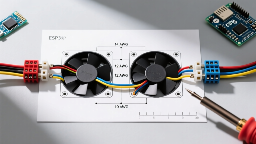
| Primary Power Wire | 10 AWG TXL (Red), SAE J1128 Compliant | $1.85 / ft | Carries solenoid trigger current from battery |
| Control Circuit Wire | 14 AWG TXL (Multiple colors) | $1.10 / ft | Ignition feed, ground triggers, and button routing |
| Terminals & Sealing | Adhesive-Lined Heat Shrink (3M FP-301), Ring/Spade | $32.00 (Kit) | Vibration-proof, corrosion-resistant terminations |
Step-by-Step Wiring Diagram Logic
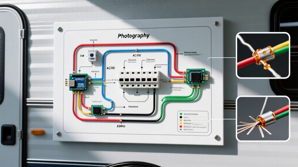
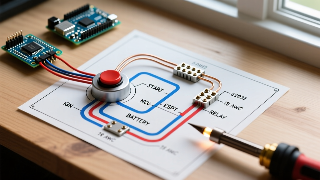
To ensure your build meets modern reliability standards, we utilize a ground-triggered relay topology. Running a ground wire to your dash button is significantly safer than routing a 12V hot wire; if the button's wiring chafes against the metal dash, a ground wire will simply short to ground harmlessly, whereas a hot wire could cause an electrical fire.
Step 1: The Main Power Feed & Master Fuse
Run a length of 10 AWG red TXL wire from the positive battery terminal (or the main starter lug) to a 30A MAXI fuse holder mounted in the engine bay. From the fuse holder, route the wire to Pin 30 (Normally Open / Power In) on your Bosch-style starter relay. Always use a crimping tool that meets IPC/WHMA-A-620 standards, such as the Knipex 97 53 14, followed by 3M adhesive-lined heat shrink to prevent moisture ingress.
Step 2: The Ignition & Neutral Safety Interlock
Your push button should only work when the ignition is in the "ON" position and the vehicle is in Park or Neutral.
- Pin 86 (Relay Coil Power): Connect a 14 AWG wire from an ignition-switched 12V source (e.g., the "IGN" terminal on your fuse block). Route this wire through your Neutral Safety Switch (NSS) before it reaches Pin 86. This ensures the relay cannot receive power unless the transmission is in a safe gear.
- Pin 85 (Relay Coil Ground): Route a 14 AWG wire from Pin 85 directly to the back of your dash-mounted momentary push button. The other terminal of the push button connects to a clean, bare-metal chassis ground.
Step 3: Triggering the Starter Solenoid
When you press the button, you complete the ground path, energizing the relay coil. The internal switch closes, sending 12V from Pin 30 to Pin 87.
Connect a 10 AWG wire from Pin 87 directly to the "S" (Start) terminal on the GM starter solenoid. This terminal requires roughly 12 to 15 amps to pull the heavy internal contactor closed, which is why 10 AWG wire and a 30A relay are mandatory. Refer to Painless Performance wiring manuals for detailed terminal mapping on specific GM Delco starters.
The Critical "R" Terminal Bypass (Don't Skip This)
Expert Warning: Classic GM vehicles utilizing points-style distributors or early HEI conversions rely on a ballast resistor wire to drop voltage to the coil during normal running (preventing point burnout). During cranking, the starter solenoid's "R" terminal sends full 12V to bypass this resistor for a hotter spark. If your push-button conversion ignores the "R" terminal, the car will crank but stall immediately upon releasing the button.
The Fix: If you are retaining a ballast resistor setup, you must wire a 1N5408 blocking diode (rated 3A, 1000V) from the ignition switch's "Crank" output wire to the "R" terminal on the solenoid. The diode's stripe must point toward the "R" terminal. This allows 12V to flow to the coil during cranking but prevents voltage from back-feeding into the ignition switch when the key is merely in the "Run" position. If you have upgraded to an MSD 6AL or similar capacitive discharge ignition system, the "R" terminal is no longer required and can be left disconnected.
Integrating an Anti-Grind Relay
Accidentally pressing the start button while the engine is already running will force the starter bendix gear into the spinning 150+ tooth flywheel, resulting in catastrophic mechanical failure and a destroyed starter motor. According to SAE J1128 automotive wiring standards, protecting high-draw inductive loads requires secondary logic circuits.
An Anti-Grind Relay monitors the alternator's output. Wire the relay's trigger to the alternator's "BAT" or "S" sense terminal. Once the alternator begins producing voltage (indicating the engine is running), the anti-grind relay opens the ground path to your push button, rendering it completely inactive until the engine is shut off.
Real-World Troubleshooting Matrix
Even with a perfect wiring diagram for push button start layouts, environmental factors in classic cars can cause issues. Use this matrix to diagnose common failure modes.
| Symptom | Probable Cause | Diagnostic & Repair Action |
|---|---|---|
| Relay clicks, but starter does not engage. | Voltage drop on Pin 30 or Pin 87 circuits; undersized wire. | Perform a voltage drop test across the 10 AWG wires while pressing the button. Replace any crimp connectors showing >0.2V drop. |
| Engine cranks but dies when button is released. | Missing "R" terminal ballast bypass; failing ignition switch. | Install 1N5408 diode to "R" terminal, or verify aftermarket CDI box is receiving switched 12V. |
| Push button does nothing; no relay click. | Neutral Safety Switch misaligned; blown dash fuse. | Bypass NSS temporarily with a jumper wire to isolate the fault. Check 14 AWG ignition feed for 12V. |
| Starter stays engaged after releasing button. | Relay contacts welded shut due to amperage spike. | Replace Bosch relay. Verify starter solenoid return spring is not fatigued. Add anti-grind relay. |
Final Routing and Validation
Once all terminations are complete, secure all engine bay wiring with high-temperature Teflon cable clamps, keeping the 10 AWG starter wires at least 4 inches away from exhaust headers. Before connecting the battery, use a digital multimeter to verify continuity from the dash button to the relay ground pin. For further reading on managing high-amperage automotive circuits and selecting the correct circuit protection devices, consult the technical resources available via Summit Racing's Expert Advice portal.
By adhering strictly to this relay-isolated, ground-triggered topology, your classic vehicle will benefit from a modern, reliable, and safe starting mechanism that eliminates the mechanical wear and voltage drops inherent in 50-year-old steering column switches.