
Understanding the Wiring Diagram for Pool Light Systems
Wiring a swimming pool light is one of the most critical electrical tasks a contractor or advanced DIYer can undertake. Because water and electricity are inherently dangerous when mixed, the National Electrical Code (NEC) Article 680 establishes rigorous safety standards for aquatic environments. Whether you are upgrading an aging 120V halogen fixture to a modern 12V LED system or installing a new build, understanding the correct wiring diagram for pool light configurations is non-negotiable.
In 2026, the vast majority of new pool installations utilize 12V LED lighting due to superior energy efficiency, lower heat output, and enhanced safety. However, legacy 120V systems are still present in many residential pools. This guide breaks down the exact wiring topology, component specifications, and NEC compliance requirements for both architectures.
⚠️ CRITICAL SAFETY WARNING: Never work on pool electrical systems without verifying that all power is disconnected at the main breaker. According to the U.S. Consumer Product Safety Commission (CPSC), faulty pool wiring and inadequate equipotential bonding are leading causes of aquatic electrocution. Always hire a licensed electrician if you are unsure about local code interpretations.
System Architecture: 12V LED vs. 120V Incandescent
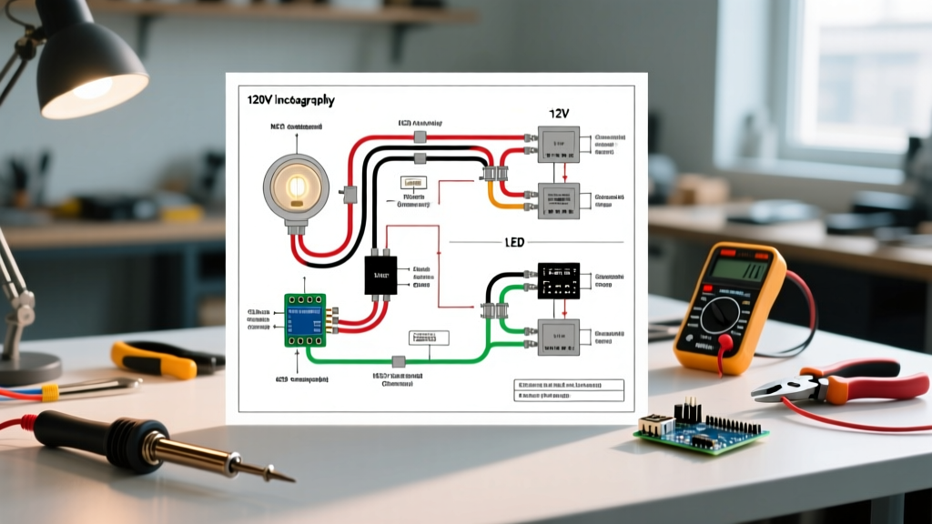
Before pulling wire, you must identify your system voltage. The wiring diagram for a 12V pool light requires a step-down transformer, whereas a 120V system runs line voltage directly to the wet niche (protected by a GFCI). Below is a technical comparison of the two primary systems used in residential pools.
| Feature | 12V LED System (Modern Standard) | 120V Halogen/Incandescent (Legacy) |
|---|---|---|
| Primary Power | 120V AC to Transformer, 12V AC to Light | 120V AC Direct to Light Fixture |
| GFCI Requirement | Required on 120V primary side of transformer | Required at breaker or inline receptacle |
| Wire Gauge (Min) | 12 AWG THWN (often 10 or 8 AWG for voltage drop) | 12 AWG THWN-2 |
| Heat Output | Minimal (safe for PVC niches) | Extreme (requires water submersion for cooling) |
| Avg. Fixture Cost | $350 - $550 (e.g., Pentair IntelliBrite 12V) | $150 - $250 (e.g., Hayward Astrolite) |
Step-by-Step Wiring Diagram for 12V Pool Lights
The following procedure outlines the standard wiring diagram for a 12V pool light system, which is the current industry standard for new construction and retrofits. For deeper code references, consult the National Fire Protection Association (NFPA) NEC Article 680 guidelines.
Phase 1: Main Panel to GFCI Breaker
- Breaker Selection: Install a 15A or 20A, 120V GFCI circuit breaker in your main electrical panel or a dedicated pool sub-panel. Standard breakers are strictly prohibited; GFCI protection is mandatory.
- Line Voltage Wiring: Run 12 AWG THWN-2 copper conductors (Black/Hot, White/Neutral, Green/Ground) through rigid PVC conduit (Schedule 40 underground, Schedule 80 where subject to physical damage) from the panel to the pool light transformer location.
Phase 2: GFCI Breaker to Step-Down Transformer
- Transformer Sizing: Select a 120V-to-12V AC pool lighting transformer (e.g., Intermatic PX300 or PX600). Ensure the transformer's VA (Volt-Amp) rating exceeds the total wattage of all connected lights by at least 20%. A single 50W LED light requires a minimum 100W transformer.
- Primary Connections: Connect the 120V Black (Hot) wire to the transformer's primary 'Hot' terminal, and the White (Neutral) to the primary 'Neutral' terminal. Connect the equipment grounding conductor to the transformer's grounding lug.
- Secondary Connections: Connect two 12 AWG (or larger) THWN wires to the transformer's 12V secondary output terminals. Polarity does not matter on standard AC magnetic transformers, but verify manufacturer specs for electronic LED drivers.
Phase 3: Transformer to Deck Junction Box
- Junction Box Placement: NEC 680.24 requires the junction box (e.g., Pentair U214) to be located at least 4 inches above grade and at least 8 feet horizontally from the pool edge, unless separated by a solid barrier.
- Conduit Routing: Run the 12V secondary wires through PVC conduit from the transformer to the junction box. Maintain strict separation between 120V line-voltage conduits and 12V low-voltage conduits to prevent inductive interference.
Phase 4: Junction Box to the Wet Niche (Light Fixture)
- Potting Compound (Cord Seal): This is the most frequently missed step. You must apply an approved potting compound (like 3M Scotchcast #2130) inside the junction box around the light's cord conductors. This prevents water from wicking up the cord conduit and flooding the transformer or panel if the light's lens seal fails.
- Wire Nuts & Grounding: Connect the 12V light cord wires to the secondary feed wires using silicone-filled, moisture-sealed wire nuts. Bond the light's bare copper ground wire to the junction box's grounding bus and the equipotential bonding grid.
- Service Loop: Leave at least 3 to 4 feet of extra cord coiled inside the wet niche behind the fixture. This 'service loop' allows you to pull the light up to the pool deck for future bulb or diode replacements without pulling new wire through the conduit.
Voltage Drop Calculations for 12V Systems
When executing your wiring diagram for pool light setups, voltage drop is the silent killer of 12V LED performance. Unlike 120V systems, 12V systems experience significant voltage drop over distance, which can cause LED flickering, color shifting, or premature driver failure.
The NEC recommends a maximum voltage drop of 3% for branch circuits. For a 12V system, 3% equals just 0.36 volts. If your transformer is located 60 feet from the junction box, and the junction box is another 40 feet from the light (100 feet total run), 12 AWG wire will result in an unacceptable voltage drop for a 50W load.
Wire Sizing Matrix for 12V Pool Lights (Max 50W Load)
| Total One-Way Distance (Transformer to Light) | 12 AWG THWN | 10 AWG THWN | 8 AWG THWN |
|---|---|---|---|
| Up to 30 Feet | Acceptable (1.5% Drop) | Optimal (0.9% Drop) | Overkill |
| 31 to 60 Feet | Fail (3.1% Drop) | Acceptable (1.9% Drop) | Optimal (1.2% Drop) |
| 61 to 100 Feet | Fail (5.2% Drop) | Fail (3.2% Drop) | Acceptable (2.0% Drop) |
Pro Tip: Always measure the total wire length, including the service loop inside the niche and the extra length required to reach the deck junction box, when calculating voltage drop.
Equipotential Bonding: The Invisible Safety Net
No wiring diagram for pool light systems is complete without addressing the equipotential bonding grid. Bonding is distinctly different from grounding. While grounding provides a path for fault current to trip the breaker, bonding connects all metallic components (pool rebar, water, ladders, light niches, and junction boxes) to the same electrical potential. This ensures that if a fault occurs, a swimmer touching the light niche and the pool ladder will not become the path of least resistance.
- Wire Specification: Use a solid 8 AWG bare copper bonding wire.
- Connections: The bonding wire must be attached to the exterior bonding lug on the metal light niche (or the designated bonding point on composite/plastic niches), the junction box, the transformer enclosure, and the pool's structural steel grid.
- Splicing: Bonding wire splices must be made using listed, irreversible connectors (like exothermic welding or specific listed split-bolt connectors) and must remain accessible or be encased in concrete.
Troubleshooting Common Pool Light Failures
Even with a perfect installation, pool lighting systems can experience issues. Use this diagnostic matrix to troubleshoot problems efficiently, referencing expert guidelines from publications like EC&M's National Electrical Code hub for code-compliant repairs.
| Symptom | Probable Cause | Diagnostic Action |
|---|---|---|
| GFCI Breaker Trips Immediately | Water intrusion in the niche, degraded cord insulation, or faulty transformer. | Megohmmeter test the light cord. Inspect the lens gasket. Disconnect transformer secondary to isolate the fault. |
| LED Light Flickers or Dims | Excessive voltage drop on the 12V secondary side or failing LED driver. | Measure AC voltage at the light niche terminals under load. If below 11.2V, upsize secondary wiring. |
| Transformer Hums Loudly | Overloaded transformer or loose lamination in magnetic core. | Verify total connected wattage does not exceed 80% of the transformer's VA rating. Tighten mounting bolts. |
| Light Works, But Colors Desync | Signal interference on multi-light 12V systems or faulty controller. | d>Ensure all lights are on the same transformer circuit. Reset the IntelliBrite or ColorLogic controller sequence. |
Final Inspection and Commissioning
Before filling the pool or turning on the power, conduct a rigorous visual and mechanical inspection. Verify that all conduit fittings are PVC-glued and watertight, the junction box cord seal has fully cured (usually 24 hours), and the 8 AWG bonding grid is continuous and unbroken. Once power is applied, use a receptacle tester with a GFCI trip function at any nearby pool receptacles to ensure the ground fault protection is actively monitoring the circuit. By strictly adhering to this wiring diagram for pool light protocols, you ensure a vibrant, long-lasting, and fundamentally safe aquatic environment.