
Why Skoolies and Camper Vans Are Ditching Roof ACs in 2026
The RV and camper van electrical landscape has shifted dramatically. Traditional 13,500 BTU roof-mounted air conditioners are notorious for drawing massive startup surges (often exceeding 3,500 watts) and requiring heavy, expensive generator setups. In 2026, the dominant trend in skoolie conversions and off-grid camper vans is installing high-efficiency residential window units—specifically inverter-driven models like the Midea U-Shaped 8,000 BTU (Model MAW08V1QWT) or reliable mechanical units like the Frigidaire FFRA051WAE. These units run between 400W and 700W continuously, making them perfectly suited for solar and lithium battery banks.
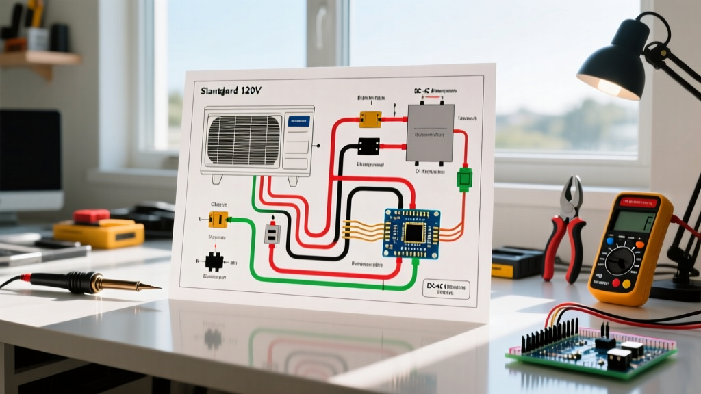
However, adapting a residential appliance to a mobile DC-to-AC environment requires strict adherence to mobile electrical codes and a deep understanding of both the appliance's internal schematics and your vehicle's AC subpanel. Below, we provide a comprehensive guide and wiring diagram for window air conditioner integration into 12V, 24V, and 48V RV inverter systems.
Decoding the Internal Wiring Diagram for Window Air Conditioner Units
Before connecting your unit to the RV's breaker panel, you must understand the internal wiring diagram for window air conditioner compressors and control boards. Residential window units typically utilize a Permanent Split Capacitor (PSC) fan motor and either a traditional reciprocating compressor or a modern variable-speed inverter compressor.
The Compressor Terminal Pinout (C, R, S)
If you are troubleshooting a unit that trips your RV's inverter, you will need to access the compressor terminal block. The standard 3-pin layout is universal across most non-inverter window ACs:
- C (Common): Receives the main 120V AC line voltage directly from the contactor or control board relay.
- R (Run): Connects to the 'HERM' (Hermetic) terminal on the dual-run capacitor and completes the main running circuit.
- S (Start): Connects to the 'S' terminal on the capacitor and the start relay (or PTC thermistor). This provides the phase-shifted torque needed to overcome the compressor's initial inertia.
Expert Warning: Never attempt to wire a hard-start capacitor kit to a modern variable-speed inverter compressor (like those found in the Midea U-Shaped series). These units use internal DC-driven BLDC motors and complex PCBs; adding an external AC start capacitor will instantly destroy the control board.
The Dual-Run Capacitor Wiring
Standard 5,000 to 8,000 BTU units use a single dual-run capacitor (typically 30+5 MFD, 370VAC). The terminals are clearly marked:
- C (Common): Jumper wire from the 120V Hot line.
- HERM (Hermetic): Wire to the Compressor 'R' (Run) terminal.
- FAN: Wire to the Fan Motor brown wire.
Vehicle Integration: The 120V AC Subpanel Diagram
Per the NFPA 1192 Standard on Recreational Vehicles, any permanently installed 120V AC appliance in a mobile vehicle must be on a dedicated, properly grounded branch circuit. You cannot simply plug a window AC into an existing RV receptacle using an extension cord; the voltage drop over 20+ feet of 14 AWG cord will cause the compressor to overheat and fail.
Step-by-Step: Wiring the RV AC Subpanel
Here is the exact wiring flow for integrating a dedicated window AC circuit into your camper van or skoolie:
- Power Source: 120V AC from either the Shore Power inlet (via a 30A main breaker) or the AC Output of your Inverter/Charger (e.g., Victron MultiPlus-II 3000VA).
- Branch Breaker: Install a dedicated 20A GFCI/AFCI breaker in your RV's AC subpanel. While the AC only draws 6 to 11 amps running, the 20A breaker accommodates the momentary Locked Rotor Amps (LRA) surge without nuisance tripping.
- Wire Selection: Run 12 AWG THHN copper wire (Black for Hot, White for Neutral, Green/Bare for Ground) through flexible liquid-tight conduit to protect against vehicle vibration and chassis chafing.
- Termination: Wire the Hot and Neutral directly to a heavy-duty 20A twist-lock receptacle (L5-20R) mounted near the AC installation window. Cut the factory AC power cord and wire a matching L5-20P plug. This prevents the cord from vibrating loose while driving.
- Chassis Grounding: Crucially, bond the metal chassis of the window air conditioner to the RV's main DC ground bus bar using a separate 10 AWG ground wire. This ensures that if a 120V hot wire shorts to the AC's metal casing, it trips the breaker immediately rather than electrifying the vehicle body.
Inverter Sizing and the 'Soft Start' Necessity
The most common failure point in off-grid RV AC wiring is undersizing the inverter. The U.S. Department of Energy notes that room air conditioners require significant startup power. To calculate your exact inverter needs, refer to the data matrix below.
| AC Unit Type (Example) | BTU Rating | Running Amps (RLA) | Startup Surge (LRA) | Min. Inverter Size | Wire Gauge |
|---|---|---|---|---|---|
| Mechanical (Frigidaire FFRA051WAE) | 5,000 | 4.0A (480W) | 18A (2,160W) | 2000W Pure Sine | 12 AWG |
| Mechanical (LG LW8016ER) | 8,000 | 6.5A (780W) | 28A (3,360W) | 3000W + Soft Start | 10 AWG |
| Inverter Compressor (Midea U-Shaped) | 8,000 | 5.5A (660W) | 8A (960W) | 1500W Pure Sine | 12 AWG |
The Pure Sine Wave Rule: Never wire a window air conditioner to a Modified Sine Wave (MSW) inverter. MSW inverters output a stepped, square-wave approximation of AC power. This causes the AC's internal run capacitors to overheat, the fan motor to hum violently, and the digital control boards to fry within hours. Always use a Pure Sine Wave inverter (like the Victron or Growatt lines).
Advanced Mod: Bypassing the Internal Thermostat for Smart 12V Control
One of the biggest issues with running a residential window AC in a camper van is short-cycling. When the internal mechanical thermostat clicks off, it cuts power to the compressor. If the ambient temperature rises and it clicks back on 30 seconds later, the equalized refrigerant pressure can stall the compressor, drawing massive LRA and tripping your inverter.
The 12V Relay Bypass Diagram
To solve this, advanced DIYers bypass the internal thermostat and control the AC via a 12V smart relay tied to a vehicle-mounted digital thermostat (like a Dometic or Victron Cerbo GX setup).
- Locate the Thermostat Switch: Open the AC's front plastic fascia. Trace the two thin wires leading from the mechanical temperature dial to the main PCB.
- Bypass the Switch: Desolder or cut these two wires and bridge them together. This tricks the AC into thinking the thermostat is permanently calling for 'Cool'.
- Wire the 12V Interrupt Relay: Splice into the main 120V Hot wire before it enters the AC's control board. Wire this Hot line through the Normally Open (NO) and Common (COM) terminals of a heavy-duty 120V AC contactor or a high-amperage solid-state relay.
- 12V Control Side: Wire the relay's 12V DC coil to your camper's smart thermostat controller. Set the controller to enforce a mandatory 5-minute compressor delay between cycles.
This modification ensures the AC's internal logic board remains powered (preventing error codes) while safely managing compressor cycle times via the vehicle's centralized 12V brain.
Troubleshooting Common Vehicle-Specific AC Wiring Failures
1. Inverter Overload During Shore Power Transfer
Symptom: The AC compressor stalls and the inverter throws an overload alarm when unplugging from shore power, even though the inverter is sized correctly.
Diagnosis: Your inverter's internal transfer switch is too slow. When shore power drops, the inverter takes 20-50ms to switch to battery power. The AC compressor loses momentum during this gap and requires a massive LRA surge to restart.
Fix: Upgrade to a hybrid inverter with a UPS-style transfer time of under 10ms (e.g., Victron MultiPlus-II), or install a dedicated SoftStartRV device on the AC's compressor terminals to flatten the startup curve.
2. Voltage Drop and Breaker Nuisance Tripping
Symptom: The 20A branch breaker trips randomly when the van is parked in direct sunlight, but works fine in the shade.
Diagnosis: Heat increases electrical resistance. If you used 14 AWG wire for a long run (over 15 feet) from the subpanel to the window, the voltage at the AC terminals may drop below 105V under load. As voltage drops, the AC draws more amps to maintain its wattage output, tripping the thermal breaker.
Fix: Replace the branch circuit wiring with 10 AWG stranded copper to minimize voltage drop, ensuring the AC receives a stable 115V-120V regardless of ambient chassis temperatures.
Final Safety Inspections
Before sealing up your camper van walls or skoolie ceiling, perform a continuity test from the window AC's metal exterior chassis to the RV's main ground lug. It must read less than 0.5 ohms. Additionally, verify that your inverter's neutral-to-ground bonding relay is functioning correctly; in mobile applications, the inverter must bond the neutral and ground when operating off-grid to ensure the AC's internal GFCI and your subpanel breakers trip correctly during a fault. By respecting both the appliance's internal schematic and the rigorous demands of mobile electrical systems, your residential window AC will provide ultra-efficient, whisper-quiet cooling for years on the road.