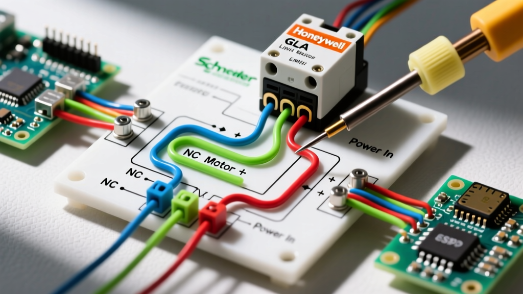

Introduction to Limit Switch Motor Control
In industrial automation and heavy-duty HVAC systems, precision and safety are non-negotiable. Whether you are controlling a conveyor belt's travel distance or an industrial damper's open/close position, interpreting and executing a wiring diagram for limit switch integration is a foundational skill for electrical technicians. A limit switch acts as the physical sentinel of your circuit, translating mechanical movement into an electrical signal to halt or reverse a motor.
This comprehensive walkthrough dissects the anatomy of a 120VAC/240VAC motor control circuit utilizing a heavy-duty limit switch. We will move beyond generic theory, providing exact torque specifications, real-world component model numbers, and 2026 pricing realities to ensure your installation is both code-compliant and operationally bulletproof.
Component Breakdown and 2026 Specifications
Before touching a wire stripper, you must verify your bill of materials. For this walkthrough, we are building a fail-safe stop circuit for a 3HP, 230VAC single-phase HVAC exhaust motor.
| Component | Model Number | Specifications | Est. 2026 Cost |
|---|---|---|---|
| Limit Switch | Honeywell GLAA01A1B | 1NC/1NO, 10A 120VAC, IP67, NEMA 1/12/13 | $58.00 |
| Contactor | Schneider TeSys LC1D09M7 | 9A, 220VAC Coil, 3-Pole | $47.50 |
| Overload Relay | Schneider TeSys LRD10 | Thermal, 4A - 6A Range | $44.00 |
| RC Snubber | Schneider RC1140 | 110-240VAC, 50/60Hz (Surge Suppression) | $14.25 |
Pre-Wiring Safety and Code Compliance
CRITICAL SAFETY WARNING: Never wire a live panel. According to OSHA's Control of Hazardous Energy (Lockout/Tagout) standards, you must isolate all power sources, apply a physical lock, and verify zero energy state with a calibrated CAT III or CAT IV multimeter before beginning termination. Furthermore, refer to NIOSH Publication 98-131 for comprehensive guidelines on preventing electrocution during industrial wiring tasks.
Ensure your wire sizing complies with the latest NFPA 70 (National Electrical Code). For a 3HP motor drawing approximately 17A at 230VAC, NEC Article 430 dictates that branch circuit conductors must be sized at 125% of the motor full-load current (FLC). Therefore, 10 AWG THHN copper wire is required for the power circuit, while 14 AWG is sufficient for the 220VAC control circuit.
Step-by-Step Wiring Walkthrough
Phase 1: The Power Circuit (Line to Load)
The power circuit delivers the high-current load to the motor. We are using a 230VAC single-phase supply, meaning we will utilize two poles of our 3-pole Schneider LC1D09M7 contactor.
- Line Side Termination: Strip 12mm of insulation from your 10 AWG supply wires. Terminate L1 and L2 into the top terminals (1/L1 and 3/L2) of the TeSys contactor. Pro Tip: Apply exactly 1.7 Nm (15 lb-in) of torque to the screw terminals. Under-torquing causes arcing; over-torquing strips the copper cage.
- Load Side to Overload: Run 10 AWG jumper wires from the bottom of the contactor (2/T1 and 4/T2) directly into the top line terminals of the TeSys LRD10 overload relay.
- Overload to Motor: Route the load side of the overload relay to your motor's junction box, ensuring your equipment grounding conductor (EGC) is bonded to the motor chassis and the panel ground bus.
Phase 2: The Control Circuit (Integrating the Limit Switch)
This is where the core logic of the wiring diagram for limit switch applications comes to life. We are wiring a 'fail-safe' stop circuit. When the mechanical actuator hits the limit switch, the circuit opens, dropping the contactor coil and halting the motor instantly.
- Control Power Source: Tap your 220VAC control power (often derived from a step-down transformer or directly from L1/L2 if the coil matches line voltage). Route the first control wire through a 2A glass fuse holder for short-circuit protection.
- Wiring the NC Contact: Connect the fused control wire to the Normally Closed (NC) terminal of the Honeywell GLAA01A1B limit switch (Terminal 21/22). Why NC? If the limit switch wire breaks or the switch fails mechanically, an NC configuration defaults to an open circuit, safely shutting down the motor. Using a Normally Open (NO) contact for a stop function is a severe safety violation.
- Contactor Coil Integration: Run a 14 AWG wire from the NC output of the limit switch to the A1 terminal on the Schneider contactor coil.
- Completing the Loop: Connect the A2 terminal on the contactor coil back to your neutral or second control power leg.
- Inductive Kickback Protection: Solder or screw the Schneider RC1140 snubber directly across the A1 and A2 coil terminals. When the limit switch opens, the collapsing magnetic field of the contactor coil generates a high-voltage spike. The RC snubber absorbs this energy, preventing micro-welding and pitting on the limit switch's internal silver-alloy contacts.
Decoding Limit Switch Contact Logic
When reviewing schematics, understanding the difference between contact configurations is vital for proper system behavior.
- SPDT (Single Pole Double Throw): Features one Common (C), one NC, and one NO terminal. Used for basic stop/start limits (like our Honeywell GLA).
- DPDT (Double Pole Double Throw): Contains two isolated circuits. Often used when a single limit switch must simultaneously cut motor power and trigger a PLC input or indicator light.
- Slow-Make / Break-Before-Make: Standard snap-action switches break the NC circuit milliseconds before making the NO circuit. This prevents short-circuiting power sources if used for motor reversal (plugging) applications.
Troubleshooting Edge Cases and Failure Modes
Even with a perfect wiring diagram for limit switch setups, field conditions introduce variables. Here is how to diagnose the three most common failure modes:
1. Contact Chatter and Bounce
Symptom: The contactor hums loudly or rapidly cycles on and off as the actuator slowly approaches the limit switch plunger.
Root Cause: Mechanical vibration or a slow-approaching actuator causing the internal snap-action spring to flutter.
Solution: Replace the standard plunger with a roller-lever actuator (e.g., Honeywell GLA01B) to ensure a fast, glancing strike. Alternatively, introduce a solid-state relay (SSR) between the limit switch and the contactor coil to eliminate mechanical bounce entirely.
2. Switch Overtravel and Mechanical Destruction
Symptom: The switch housing cracks, or the internal contacts weld shut after weeks of operation.
Root Cause: The machine's momentum carries the actuator past the switch's maximum overtravel rating (typically 0.120 inches for standard GLA switches).
Solution: Install a physical mechanical hard-stop on the machine chassis exactly 0.050 inches before the limit switch reaches its maximum depression depth. Never rely on the limit switch itself to act as the physical brake for heavy moving mass.
3. Environmental Ingress (NEMA vs. IP Ratings)
Symptom: Intermittent faults, corrosion on terminals, or short circuits in washdown environments.
Root Cause: Using a NEMA 1 (indoor, dust-light) switch in a high-humidity or washdown area.
Solution: Upgrade to a NEMA 4X / IP67 rated switch with fluorosilicone seals. Ensure conduit hubs are sealed with duct seal compound to prevent moisture from wicking through the stranded wire capillaries directly into the switch terminal block.
Frequently Asked Questions
Can I wire a limit switch directly to a 3HP motor without a contactor?
No. The Honeywell GLAA01A1B is rated for 10A resistive, but motor loads are highly inductive. A 3HP motor at 230V draws roughly 17A FLC, and its locked-rotor starting current can exceed 100A. Wiring the switch directly will instantly weld the contacts and destroy the switch. Always use the limit switch to control a contactor coil or a solid-state relay.
How do I test the limit switch wiring before applying main power?
Use a multimeter in continuity mode. With the power locked out, place your probes across the limit switch NC terminals. You should read near 0.0 ohms. Manually depress the actuator; the meter should read 'OL' (Open Loop). Next, check the contactor coil resistance (typically 10 to 40 ohms for a 220VAC coil) to ensure the coil is not shorted before energizing the control circuit.


