
Introduction to the Sportsman 500 Power Distribution Network
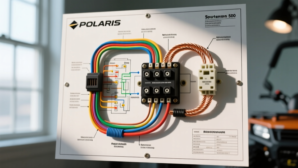
When you first unroll the wiring diagram for Polaris Sportsman 500, the sheer number of ground points, stator wires, and accessory loops can be overwhelming. However, from a 'Panel & Breaker Guide' perspective, the most critical section of this schematic is the power distribution panel and the circuit breaker network. Unlike a static residential breaker box, an ATV's fuse panel is subjected to high-frequency vibration, extreme temperature fluctuations, and frequent water and mud ingress. Understanding how power flows from the battery, through the main breaker, and into the blade fuse block is essential for both field repairs and custom accessory installations.
In this comprehensive guide, we will decode the fuse and breaker architecture of the Polaris Sportsman 500 (covering both the High Output carbureted and Electronic Fuel Injection models). We will explore exact amperage ratings, wire color codes, and the engineering logic behind the winch circuit breaker, ensuring you have the actionable data needed to troubleshoot or upgrade your rig in 2026 and beyond.
Anatomy of the Main Power Distribution Panel
The primary power distribution on the Sportsman 500 begins at the battery. According to standard DC wiring practices and the Polaris Off-Road Owner's Manuals, the main positive cable routes directly to the starter solenoid. However, before power reaches the main harness, it passes through a primary high-amperage fuse or main circuit breaker.
Main Battery Fuse vs. Accessory Breakers
On most Sportsman 500 EFI models, you will find a 30A or 40A main blade fuse located in a sealed inline holder within 6 inches of the battery positive terminal. This main fuse protects the entire vehicle wiring harness from a catastrophic short circuit. If this fuse blows, the ATV will have absolutely no electrical power—no dash lights, no fuel pump prime, and no starter engagement.
Conversely, high-draw accessories like winches do not route through this main fuse or the standard fuse box. Instead, they utilize dedicated auto-reset circuit breakers connected directly to the battery terminals. This separation ensures that a stalled winch motor does not blow the main vehicle fuse and strand you in the backcountry.
Sportsman 500 EFI Fuse Box Pinout & Amperage Chart
The secondary fuse panel is typically located under the front storage pod or beneath the seat, depending on the specific model year. This panel uses standard ATO/ATC automotive blade fuses. Below is the standard pinout and amperage breakdown derived from the factory wiring diagram for Polaris Sportsman 500 EFI models.
| Circuit Function | Fuse Rating | Typical Wire Color | Failure Symptom |
|---|---|---|---|
| ECU / EFI System | 15A | Red/Yellow | Engine cranks but will not start; no fuel pump whine. |
| Headlights (High/Low) | 15A | White/Black | Total loss of front illumination; dash high-beam indicator off. |
| Taillights & Dash | 10A | Orange/White | Rear running lights out; speedometer backlight dead. |
| Cooling Fan | 15A | Green/Red | Engine overheats at low speeds; fan relay clicks but fan doesn't spin. |
| 12V Accessory Outlet | 10A | Purple | Plugged-in GPS or phone charger loses power. |
Decoding the Wiring Diagram for Polaris Sportsman 500: The Winch Breaker
One of the most common reasons enthusiasts study the wiring diagram for Polaris Sportsman 500 is to install or troubleshoot a front-mounted winch. The factory Polaris 2500lb and 3500lb winch kits (such as part number 2835868) require a dedicated 50A or 60A auto-reset circuit breaker.
Expert Insight: Never wire a winch contactor directly to the battery without an inline breaker. A 2500lb winch under maximum load can experience an inrush current spike exceeding 45 amps. If the winch stalls or the contactor welds itself shut, the wiring will melt and cause a lithium or AGM battery fire within seconds. Always consult Blue Sea Systems Technical Support guidelines for DC motor circuit protection when sizing your breaker.
How the Auto-Reset Breaker Functions
The circuit breaker used in the Sportsman 500 winch circuit is typically a thermal, auto-resetting type. Inside the metal housing, a bimetallic strip bends when heated by excessive current (over 50A), breaking the physical connection and cutting power to the winch contactor. Once the metal cools (usually within 10 to 30 seconds), it snaps back into place, restoring the circuit. This is crucial for off-road recovery, as it allows the winch to cool down during heavy pulls without requiring the user to manually swap a blown fuse in muddy conditions.
Step-by-Step: Troubleshooting Panel & Breaker Failures
When your Sportsman 500 exhibits electrical gremlins, follow this systematic troubleshooting flow to isolate the failure to the panel or breaker level.
1. The Voltage Drop Test (Breaker Health)
Auto-reset breakers degrade over time due to internal corrosion and thermal fatigue. To test the winch breaker:
- Set your digital multimeter to DC Volts.
- Place the red probe on the battery-side stud of the breaker and the black probe on the load-side stud.
- Activate the winch under a light load.
- Passing Grade: A voltage drop of less than 0.1V.
- Failing Grade: A drop greater than 0.5V indicates high internal resistance. The breaker must be replaced immediately, even if it hasn't physically tripped.
2. Inspecting the Fuse Panel for Micro-Corrosion
The Sportsman 500 is frequently exposed to water crossings. The factory fuse box relies on a rubber compression seal to keep moisture out. Over years of use, this seal flattens, allowing humid air to enter. This causes galvanic corrosion on the tin-plated copper fuse blades. If you pull a fuse and see a powdery white or green residue on the legs, the panel is compromised. Clean the contacts with electrical contact cleaner and apply a thin layer of dielectric grease to prevent future oxidation.
3. Parasitic Draw Testing at the Main Panel
If your battery is dead after a week of sitting, the fuse panel may be harboring a parasitic draw. Disconnect the negative battery terminal and wire your multimeter (set to 10A DC) in series between the negative post and the disconnected cable. With the key off, a healthy Sportsman 500 should draw less than 2 milliamps (0.002A). If you see a draw of 50mA or higher, begin pulling fuses from the distribution panel one by one. When the amperage drops to near zero, you have identified the faulty circuit (often a stuck cooling fan relay or a shorted 12V accessory socket).
Upgrading to a Marine-Grade DC Breaker Panel
For riders who frequently submerge their ATVs or run extensive auxiliary lighting, the factory plastic fuse box is often insufficient. As of 2026, the industry standard for extreme-duty ATV builds is upgrading to a marine-grade power distribution module.
Cost & Component Breakdown for the Upgrade
- Blue Sea Systems ST Blade Fuse Box (6-Circuit): ~$35 - $45. Features independent blade fuses, a built-in negative bus bar, and a silicone splash guard.
- Marine-Grade Tinned Copper Wire (10 AWG): ~$1.50 per foot. Tinning prevents the black-wire corrosion common in standard automotive copper wire.
- Adhesive-Lined Heat Shrink Terminals: ~$15 for a 50-piece kit. Essential for sealing out moisture at the crimp joints.
- Total Upgrade Cost: Generally under $75, yielding a massive improvement in long-term electrical reliability.
Frequently Asked Questions (FAQ)
Where is the main fuse located on a Polaris Sportsman 500 HO?
On the carbureted High Output (HO) models, the main 30A inline fuse is typically located inside a small rubber boot on the red positive cable, situated just a few inches from the battery positive terminal, often tucked behind the front grille or under the seat depending on the exact year.
Can I replace the 50A winch breaker with a standard blade fuse?
No. Standard ATO blade fuses are not designed to handle the massive inrush currents and sustained high-draw amperage of a winch motor. A blade fuse will blow prematurely under heavy load or, worse, melt the fuse holder. Always use a properly rated stud-mounted auto-reset circuit breaker.
Why does my Sportsman 500 cooling fan fuse keep blowing?
If the 15A cooling fan fuse repeatedly blows, the issue is rarely the fuse itself. The most common culprit is a failing fan motor drawing excessive amperage due to internal bearing wear, or debris (mud, sticks) physically jamming the fan blades, causing the motor to stall and spike the current draw past the 15A threshold. Inspect the fan shroud and test the motor's amp draw directly before replacing the fuse panel wiring.