
The Hidden Value of the Panel Schedule in Diagnostics
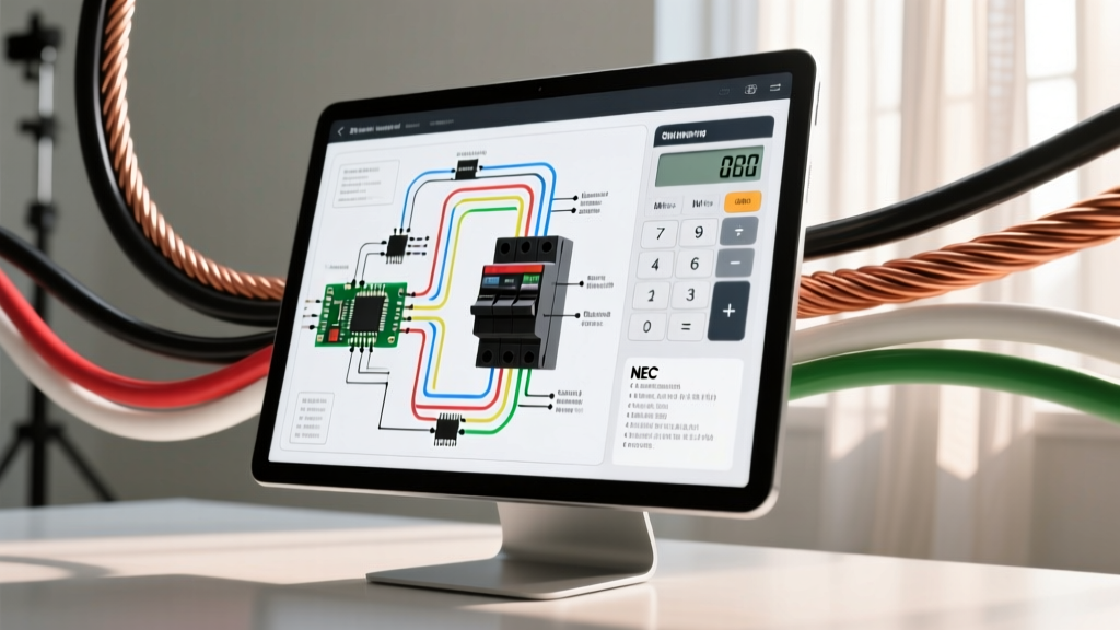
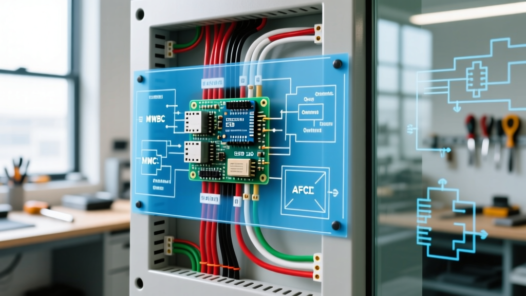
Opening an enclosure to begin troubleshooting wiring electrical panel faults without consulting the schematic is akin to performing surgery without an X-ray. While many DIYers and junior electricians rely solely on the faded, handwritten tape labels on the deadfront, a proper engineered panel schedule or single-line diagram provides critical diagnostic data. It reveals circuit topology, breaker sizing, wire gauge expectations, and phase balancing—information that is entirely invisible when you are just staring at a row of molded case breakers.
In 2026, with the widespread enforcement of the 2023 National Electrical Code (NEC) and the proliferation of smart panels, understanding how to cross-reference physical symptoms with your panel diagram is the fastest way to isolate ghost voltages, nuisance trips, and thermal failures. According to OSHA's electrical safety standards, working on energized equipment requires a thorough hazard assessment, which is impossible to conduct accurately without knowing the upstream and downstream circuit architecture mapped out in your diagrams.
Safety Directive: Never remove a panel deadfront without proper PPE (NFPA 70E Category 2 minimum) and a verified CAT III or CAT IV multimeter. Always use the diagram to identify the main service disconnect before exposing bus bars.
Decoding the Panel Schedule for Rapid Fault Isolation
Before you even unscrew the cover, locate the panel schedule. In residential settings, this is often a basic directory. In commercial or advanced residential setups (like those with Eaton or Schneider Electric smart hubs), it is a detailed matrix. Here is what you must extract from the diagram before testing:
- Breaker Pole Configuration: Identifies if a circuit is single-phase 120V, two-pole 240V, or a Multi-Wire Branch Circuit (MWBC).
- Wire Gauge & Conductor Count: Tells you if you should expect 14/2, 12/3, or THHN in conduit.
- Specialty Breaker Types: Notes whether a circuit requires a Combination AFCI (CAFCI), Dual Function (DF), or standard thermal-magnetic breaker.
- Bus Phase Allocation: Odd numbers typically land on Phase A (or L1), and even numbers on Phase B (or L2). This is vital for load balancing and 240V troubleshooting.
Scenario 1: Tracing Multi-Wire Branch Circuit (MWBC) Open Neutrals
The Symptom: A homeowner reports that lights in the kitchen are blindingly bright, while the microwave on the adjacent counter won't start and smells like burning ozone.
The Diagram Insight: You check the panel schedule and see Circuits 14 and 16 are tied together with a handle tie, fed by a 2-pole 20A breaker. The diagram notes "12/3 NM-B". This confirms an MWBC sharing a single neutral conductor on a 240V split-phase system.
The Troubleshooting Execution: An open neutral on an MWBC forces the two 120V hot legs into a series circuit. The voltage divides based on the resistance of the connected loads. Using a Fluke 117 True-RMS multimeter (approx. $230), you measure Line-to-Neutral at the receptacle. Instead of 120V, Circuit 14 reads 185V and Circuit 16 reads 55V. The diagram saved you from assuming a utility transformer failure; you now know exactly where to look: a loose neutral pigtail in the first junction box downstream of the panel, or a failed neutral termination on the panel's ground/neutral bar.
Scenario 2: Identifying Nuisance Trips on AFCI/GFCI Breakers
The Symptom: A 15A CAFCI breaker feeding a dedicated dining room receptacle trips randomly, usually when the refrigerator compressor kicks on in the adjacent kitchen.
The Diagram Insight: The schematic shows Circuit 3 (Dining Room) is a CAFCI, but it also reveals that the physical routing of the 12/2 cable runs parallel through the same ceiling joists as Circuit 5 (Kitchen Small Appliance). Furthermore, the diagram confirms Circuit 5 is a standard GFCI receptacle-protected circuit, not a breaker-protected one.
The Troubleshooting Execution: CAFCI breakers are highly sensitive to high-frequency noise and cross-talk. Because the diagram shows the parallel routing, you can deduce that the inductive spike and EMI (Electromagnetic Interference) from the refrigerator compressor starting is coupling into the unshielded dining room cable, causing the CAFCI's microprocessor to misinterpret the noise as a series arc. The fix isn't replacing the breaker; it's rerouting the wiring or upgrading to shielded cable in that specific joist bay.
Scenario 3: Voltage Drop and Wire Gauge Mismatches
When troubleshooting a motor that hums but won't start, or a heater that underperforms, voltage drop is the prime suspect. The Fluke guide on testing for voltage drop emphasizes measuring at the source and the load simultaneously. However, your panel diagram provides the baseline.
If the diagram specifies a 30A breaker with 10 AWG wire for a workshop subpanel feed located 110 feet away, a quick calculation reveals a severe design flaw. 10 AWG copper over 110 feet at a continuous 24A load will result in a voltage drop exceeding 5%, starving the equipment. The diagram allows you to diagnose the root cause as an undersized conductor rather than a failing motor.
Critical Termination Torque Specifications (2026 NEC Compliance)
One of the most common causes of panel fires and mysterious voltage fluctuations is loose terminations. NEC Article 110.14(D) strictly mandates the use of calibrated torque tools. Guessing the tightness by "feel" is a code violation and a massive liability. When your diagram leads you to a suspected loose connection, use the manufacturer's exact specifications.
| Manufacturer / Model | Wire Range (AWG) | Required Torque (in-lbs) | Common Failure Mode if Under-Torqued |
|---|---|---|---|
| Square D (Schneider) QO | 14 - 10 | 35 in-lbs | Thermal melting of breaker casing; high resistance arcing. |
| Square D (Schneider) QO | 8 - 2 | 45 in-lbs | Voltage drop on heavy loads (HVAC, EV chargers). |
| Eaton BR | 14 - 10 | 35 in-lbs | Neutral bar overheating; ghost voltages on MWBCs. |
| Siemens QP | 14 - 10 | 45 in-lbs | Bus bar pitting; nuisance thermal trips. |
| GE (ABB) THQL | 14 - 10 | 35 in-lbs | Aluminum wire creep (if older panels); localized heating. |
Note: Always verify torque values against the specific breaker's printed label or the manufacturer's current 2026 datasheet, as specifications can vary by exact model number and manufacturing year.
Step-by-Step Diagnostic Workflow Using Schematics
- Visual Map & Verify: Match the physical breaker layout to the panel schedule. Look for undocumented field modifications (e.g., a 20A breaker installed where the diagram calls for a 15A).
- Check for Code Violations on the Neutral Bar: NEC Article 408.41 prohibits double-tapping neutral conductors under a single lug. The diagram tells you how many circuits should terminate on the bar. If you count 42 circuits on the diagram but see 45 wires on the neutral bar, you have found illegal double-taps causing neutral overload.
- Perform Source-to-Load Voltage Testing: With the panel energized and PPE donned, measure Line-to-Ground and Neutral-to-Ground at the breaker terminal. A reading greater than 2V on Neutral-to-Ground indicates a high-resistance neutral upstream or an overloaded neutral bar.
- Thermal Imaging Correlation: Use a thermal camera (like the FLIR E8-XT) to scan the bus bars. Cross-reference hot spots with the diagram to determine if the heat is from a loose termination (torque issue) or an overloaded circuit (load balancing issue).
Essential Tools for the Modern Troubleshooter
To properly execute diagram-assisted troubleshooting, your toolkit must meet current industry standards:
- Klein Tools 32500TORQ Torque Screwdriver ($115 - $130): Essential for meeting NEC 110.14(D) requirements when re-terminating wires discovered to be loose during your diagnostic sweep.
- Fluke 117 True-RMS Multimeter ($220 - $250): Features VoltAlert non-contact voltage detection and low-impedance (LoZ) mode to eliminate ghost voltage readings when tracing open neutrals identified on your MWBC diagrams.
- Southwire Circuit Tracker ($90 - $110): Invaluable when the panel diagram is missing or entirely inaccurate, allowing you to map the panel from a downstream receptacle without cutting power to the whole building.
Final Thoughts on Schematic-Driven Diagnostics
Troubleshooting a modern wiring electrical panel requires moving beyond simple trial-and-error breaker flipping. By treating the panel schedule and circuit diagrams as your primary diagnostic map, you can predict failure modes, identify hidden code violations like shared neutrals or undersized conductors, and apply precise, data-driven fixes. Always consult the NFPA 70 (National Electrical Code) for the most current termination and routing standards, and never bypass the safety protocols required when working near exposed, energized bus bars.