
Understanding the 3 Speed Electric Fan Motor Wiring Diagram
Wiring a Permanent Split Capacitor (PSC) motor is a fundamental skill for HVAC technicians and advanced DIYers. When dealing with a standard 1/4 HP to 1/2 HP blower motor—such as the widely used Fasco A067 or Dayton 1TDR9 series—understanding the internal winding taps is critical. A 3 speed electric fan motor wiring diagram maps out the main and auxiliary windings, allowing you to manipulate the magnetic field strength and, consequently, the motor's RPM. Unlike ECM (Electronically Commutated Motors) that require proprietary control boards, PSC motors rely on straightforward analog voltage routing through physical speed taps. This guide provides a comprehensive, step-by-step walkthrough to safely wire, test, and commission a 3-speed PSC fan motor, ensuring optimal airflow and long-term reliability.
Critical Safety Protocols: Lockout and Verification
Before stripping a single wire, you must eliminate the risk of arc flash and electrocution. Working on 120V or 240V HVAC circuits requires strict adherence to safety standards. According to OSHA's Control of Hazardous Energy guidelines, simply flipping a wall switch or thermostat is insufficient. You must perform a formal Lockout/Tagout (LOTO) procedure at the main breaker panel or the local disconnect switch.
- Step 1: Turn off the dedicated HVAC breaker and apply a physical padlock and LOTO tag.
- Step 2: Use a True-RMS multimeter (such as the Fluke 117) to test for zero voltage. Place one probe on the ground and the other on the line terminal, then reverse the probes to verify the meter's functionality.
- Step 3: Discharge the run capacitor. Even with power disconnected, a 370V capacitor can hold a lethal charge. Use a 20,000-ohm, 5-watt bleeder resistor across the capacitor terminals for 10 seconds before handling.
Anatomy of a 3-Speed PSC Motor: Windings and Taps
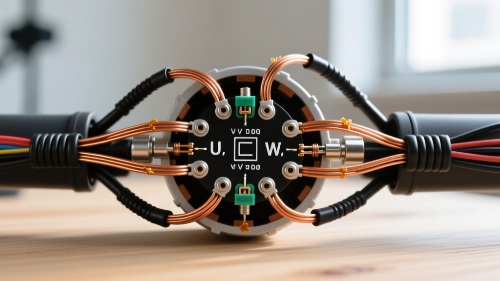
To interpret a 3 speed electric fan motor wiring diagram, you must understand how speed is controlled. PSC motors achieve different speeds by introducing resistance into the main winding circuit via physical taps. When you select 'Low' speed, the current travels through the entire length of the main winding, maximizing resistance and reducing the magnetic field strength, which lowers the RPM. When you select 'High' speed, the current bypasses a portion of the winding, reducing resistance and allowing the motor to spin at its maximum rated RPM.
Standard Wire Color Matrix and Resistance Values
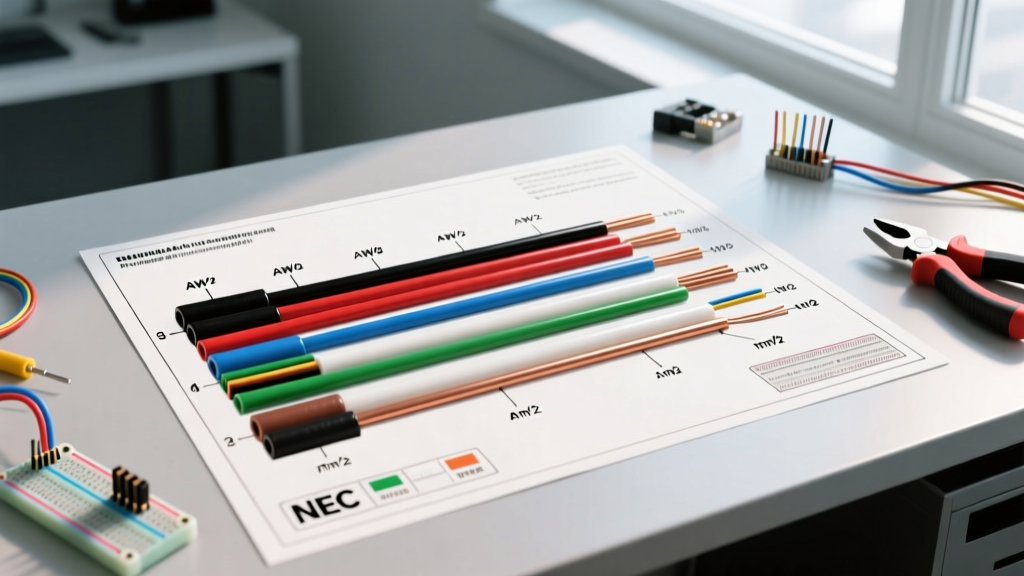
While manufacturers like Fasco, Genteq, and Century have slight variations, the industry standard color code for a 115V/230V 3-speed PSC motor typically follows this matrix. Always verify against the specific nameplate diagram on your motor housing.
| Function | Standard Wire Color | Connection Point | Relative Resistance to Common |
|---|---|---|---|
| High Speed | Black | Fan Relay / Speed Switch | Lowest Ohms (e.g., 2-4 Ω) |
| Medium Speed | Blue | Fan Relay / Speed Switch | Medium Ohms (e.g., 5-8 Ω) |
| Low Speed | Red | Fan Relay / Speed Switch | Highest Ohms (e.g., 9-14 Ω) |
| Common / Neutral | White | Neutral Bus / Line 2 | N/A (Baseline Reference) |
| Capacitor Run 1 | Brown | Run Capacitor (Herm/Fan) | High Ohms (Auxiliary Winding) |
| Capacitor Run 2 | Brown w/ White Stripe | Run Capacitor (Common) | High Ohms (Auxiliary Winding) |
Step-by-Step Wiring Walkthrough
For this walkthrough, we are wiring a standard 1/4 HP, 800 RPM, 115V PSC blower motor using a 5 MFD / 370V round run capacitor (such as the Genteq 97F9838, typically priced between $12 and $18). We will use 14 AWG THHN stranded copper wire for the circuit connections, which is rated for 15-amp circuits per NFPA 70 (National Electrical Code) Article 310.
Step 1: Wire the Run Capacitor
The auxiliary winding requires a phase shift to generate starting torque and maintain running efficiency. This is achieved via the run capacitor.
- Locate the two brown wires extending from the motor casing. These are your auxiliary winding leads.
- Connect the solid Brown wire to the 'FAN' or 'HERM' terminal on your 5 MFD run capacitor using a 1/4-inch insulated female spade connector.
- Connect the Brown wire with a white stripe to the 'C' (Common) terminal on the same capacitor.
- Expert Tip: Do not connect the capacitor wires to the line voltage or the speed switch. The capacitor operates strictly in a closed loop with the auxiliary winding.
Step 2: Connect the Common (Neutral) Lead
The white wire serves as the common return path for the main winding. Connect the motor's White wire to the neutral bus bar in your control panel, or to the L2 terminal if you are wiring a dedicated 240V contactor setup where one leg acts as the common return. Ensure this connection is torqued to the manufacturer's specification (usually 12-15 in-lbs) to prevent arcing and voltage drop.
Step 3: Route the Speed Taps
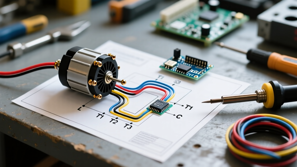
This is where the 3 speed electric fan motor wiring diagram becomes actionable. You must route the Black, Blue, and Red wires to your fan speed selector switch or control board relays.
- Black (High): Connect to the 'HIGH' or 'COOL' terminal on the fan center/relay. This is the default speed for air conditioning.
- Blue (Medium): Connect to the 'MED' terminal. Often used for continuous low-level circulation or specific heat pump staging.
- Red (Low): Connect to the 'LOW' or 'HEAT' terminal. Lower speeds are preferred for heating to allow the air to absorb more heat from the heat exchanger before entering the living space.
Critical Warning: Never energize more than one speed tap simultaneously. Applying voltage to both the Black and Red wires at the same time will create a short circuit across the internal winding taps, resulting in immediate motor burnout. Furthermore, if you are only using two speeds (e.g., High and Low), the unused Medium (Blue) tap MUST be capped with a wire nut and electrical tape. Leaving an unused tap exposed can result in back-feeding voltage, which will destroy the motor windings.
Step 4: Connect the Line Voltage (Hot)
Connect your 120V Line (Hot) supply from the breaker or contactor to the common input terminal of your fan speed switch. The switch will then route this voltage to the selected speed tap (Black, Blue, or Red) based on the thermostat's call for heating or cooling.
Troubleshooting Common Failure Modes
Even with a perfect wiring execution, components degrade. According to the U.S. Department of Energy's Motor Systems guide, improper maintenance and electrical faults account for the majority of premature motor failures. Here is how to diagnose issues using a digital multimeter.
1. Dielectric Breakdown in the Run Capacitor
Capacitors dry out over time due to thermal stress. A 5 MFD capacitor has a standard tolerance of ±6%. If your capacitance meter (like a Fieldpiece HM4) reads below 4.7 MFD, the capacitor is failing. Symptoms include the motor humming loudly without spinning, or running at half-speed and overheating. Replace the capacitor immediately; continuing to run a motor with a weak capacitor will fry the auxiliary winding.
2. Open Auxiliary Winding
If the motor refuses to start but spins freely by hand, test the brown wires. Set your multimeter to Ohms (Ω). Place the probes on the solid brown wire and the brown/white striped wire. You should read a specific resistance value (typically between 15 and 30 ohms depending on the motor size). If the meter reads 'OL' (Open Loop) or infinite resistance, the internal thermal overload has tripped permanently, or the auxiliary winding wire has snapped inside the casing. The motor must be replaced.
3. Shorted Main Winding Taps
If the breaker trips immediately upon energizing the High speed tap, you likely have a short to ground. Measure the resistance between the Black (High) wire and the motor's bare metal casing. The reading must be infinite ('OL'). Any reading below 500 kΩ indicates degraded winding insulation, often caused by moisture ingress or severe overheating.
Expert Tips for Long-Term Reliability
To ensure your installation meets professional standards and lasts for decades, follow these final mechanical and electrical best practices:
- Use Ratcheting Crimpers: Never use needle-nose pliers to crimp spade connectors. Use a ratcheting crimper (like the Titan 11500) to ensure a gas-tight connection that will not vibrate loose during motor operation.
- Apply Heat Shrink Tubing: For any splices made outside of a junction box, use adhesive-lined marine-grade heat shrink tubing rather than standard vinyl electrical tape, which degrades and unravels in the high-heat environment of an HVAC air handler.
- Vibration Isolation: Ensure the motor is mounted with intact rubber grommets. Excessive vibration transfers to the wiring harness, leading to metal fatigue and eventual wire breakage at the crimp joints.
By strictly adhering to this 3 speed electric fan motor wiring diagram walkthrough, verifying your connections with precision test equipment, and respecting NEC safety codes, you will achieve a safe, efficient, and highly reliable blower motor installation.