
Decoding the Toyota Camry Electrical Architecture
When diagnosing modern vehicle electronics, accessing a reliable toyota camry electrical wiring diagram is only the first step. For DIYers and professional technicians alike, understanding how those diagrams translate to physical components—specifically the junction blocks, fuse panels, and high-current circuit breakers—is where true diagnostic success lies. Whether you are working on an XV50 (2012–2017), an XV70 (2018–2023), or the newest XV80 (2024+) generation, the Camry utilizes a complex Multiplex Communication System (CAN bus) integrated with high-amperage power distribution panels.
This guide focuses strictly on the "Panel & Breaker" aspect of the Camry’s electrical system. We will bypass basic bulb replacements and dive deep into the Engine Room Junction Blocks (ERJB), Instrument Panel (IP) integration relays, and the specific circuit breakers that protect the vehicle's most critical high-draw systems.
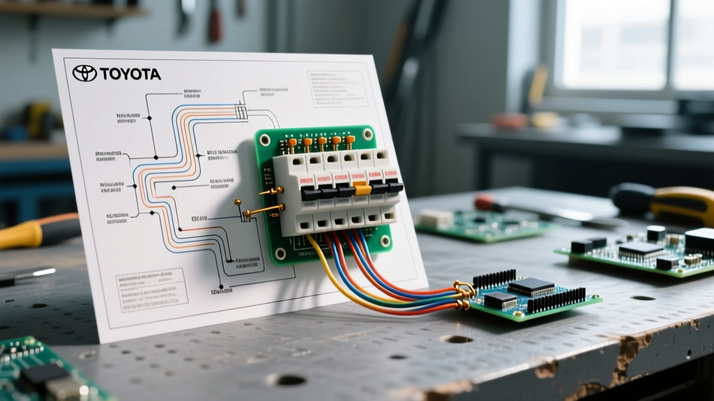
Wiring Diagram Color Codes & Topology
Before opening a panel, you must understand how Toyota represents power distribution on their factory schematics. According to the diagnostic standards outlined by the National Institute for Automotive Service Excellence (ASE), interpreting wire color codes and topology markers is critical for tracing a circuit from the battery to the breaker, and finally to the load.
- Red / White Tracer: Constant battery power (B+), typically routed directly from the main 120A alternator fuse or battery terminal.
- Green / Black Tracer: Chassis ground points. Toyota uses specific ground codes (e.g., IG1, IG2, or body grounds like "BE").
- Yellow / Blue: CAN-High and CAN-Low multiplex communication lines connecting the Body ECU to the engine control module.
- Solid Black Lines with a Circle: Indicates a splice point or a junction block pin connection, not a physical connector.
Primary Junction Blocks & Fuse Panel Locations
The Camry does not rely on a single fuse box. Instead, power is distributed through several distinct Junction Blocks (J/B). Below is a breakdown of the primary panels, their designations on the wiring diagram, and the critical breakers housed within them.
| Panel Location | Diagram Designation | Key Fuses / Breakers | Common Failure Symptom |
|---|---|---|---|
| Engine Room (Left Fender) | ERJB No. 1 | EFI Main (20A), HTR (50A J-Case) | No-start condition, HVAC blower dead |
| Engine Room (Right Fender) | ERJB No. 2 | ABS No. 1 (50A), AM2 (30A) | ABS/VSC warning lights, steering lock failure |
| Instrument Panel (Lower Dash) | IP J/B (Integration Relay) | CIG (15A), ECU-IG1 (10A Low-Profile Mini) | Dash accessories dead, OBD2 port no power |
| Trunk Area (Hybrid Models) | Hybrid Battery J/B | System Main Relay (SMR), HV Main Fuse | "Check Hybrid System" alert, vehicle immobilized |
Critical Circuit Breakers & High-Current Relays
While standard blade fuses protect low-amperage circuits (like interior lighting or audio), the Camry relies on heavy-duty circuit breakers and J-Case fuses for high-draw components. When consulting your toyota camry electrical wiring diagram, pay special attention to these high-current nodes:
1. The Cooling Fan Circuit Breaker (RDI & CDS Fans)
The radiator and condenser fan motors can draw upwards of 25 to 35 amps each upon startup. Toyota protects these circuits using 40A and 50A J-Case fuses located in the ERJB. Unlike standard Mini fuses, J-Case fuses have a higher time-delay tolerance to handle the initial inrush current of the fan motors without blowing. Pro-Tip: Never replace a blown 40A J-Case fuse with multiple smaller fuses jumpered together; this bypasses the time-delay engineering and will melt the 10 AWG wiring harness.
2. The System Main Relay (SMR) in Hybrid Models
For Camry Hybrids, the SMR is essentially a massive, computer-controlled circuit breaker that connects the 244.8V (or higher in newer generations) traction battery to the inverter. The wiring diagram will show the SMR coil being energized by the Hybrid Vehicle Control ECU. If the SMR fails to close, the vehicle will not enter "Ready" mode. Testing the SMR requires checking the 12V trigger signal at the coil pins while monitoring the high-voltage side with a CAT III rated multimeter.
3. Power Seat Circuit Breakers
The power seat motors are protected by 30A circuit breakers, often located in the under-dash IP J/B. These are thermal breakers; if the seat motor binds and draws excessive current, the breaker trips and resets automatically once it cools. If a power seat works intermittently and then dies completely for a few minutes, the breaker is doing its job—the fault lies in the mechanical seat tracks, not the wiring.
Diagnostic Warning: According to safety bulletins tracked by the National Highway Traffic Safety Administration (NHTSA), modifying or bypassing high-amperage OEM circuit breakers in the engine bay has been linked to electrical fires. Always verify the exact amperage and J-Case footprint before sourcing replacements.
Step-by-Step Breaker & Relay Troubleshooting Protocol
When the wiring diagram points to a specific relay or breaker, follow this exact diagnostic sequence to isolate the fault without throwing unnecessary parts at the vehicle.
- Visual & Tactile Inspection: Remove the suspect relay or J-Case fuse. Look for green crust (copper sulfate corrosion) on the terminals. Feel the fuse body; if the plastic is melted or warped, the circuit has been subjected to prolonged thermal overload, indicating a binding mechanical load downstream.
- Voltage Drop Test (Live Circuit): Using a digital multimeter (e.g., Fluke 117), set it to DC Volts. Place the red probe on the battery side of the fuse/breaker terminal and the black probe on the load side. A healthy breaker under load should show a voltage drop of less than 0.1V. A reading of 0.5V or higher indicates internal resistance and a failing breaker.
- Relay Coil Resistance Check: Pull the relay (e.g., the EFI Main relay). Locate pins 85 and 86 (the coil). Measure resistance across them. A standard Toyota 12V relay coil should read between 60 and 120 ohms. A reading of OL (Open Line) means the internal coil is broken.
- Switch Side Continuity: Apply 12V power and ground to pins 85 and 86 using a fused jumper wire. You should hear an audible click. Check continuity across pins 30 and 87. Resistance must be under 0.5 ohms. Anything higher indicates pitted internal contacts.
Common Failure Modes in Camry Wiring & Panels
Through years of field diagnostics, specific failure patterns emerge across different Camry generations. Being aware of these will save you hours of tracing wires.
XV50 Water Ingress in the A-Pillar
A well-documented issue in the 2012–2017 generation involves the cowl drain near the passenger side windshield clogging. Water backs up and drips directly onto the Instrument Panel Junction Block (IP J/B) located in the passenger kick panel. This causes severe corrosion on the multiplex body ECU pins, leading to phantom battery drains, erratic power window behavior, and CAN bus communication codes (U0100 series). Fix: Clear the cowl drains and treat the J/B connectors with dielectric grease or CRC QD Electronic Cleaner.
Parasitic Draw from the Integration Relay
Modern Camrys feature dozens of control modules. When the car is locked, these modules must "go to sleep" within 10 to 15 minutes. A healthy Camry should have a parasitic draw of less than 50mA (0.05A) once asleep. If the Integration Relay (which houses the Body ECU) fails internally, it may keep the CAN bus awake, resulting in a dead 12V battery after 48 hours of sitting. Diagnose this by pulling the "ECU-B" fuse in the engine bay; if the draw drops from 400mA to 30mA, the Body ECU/Integration Relay is the culprit.
Sourcing OEM Wiring Diagrams & Service Data
While aftermarket forums provide general advice, accurate breaker and panel troubleshooting requires factory-level schematics. The Toyota Technical Information System (TechInfo) is the official portal for OEM wiring diagrams, connector pinouts, and Technical Service Bulletins (TSBs). A short-term subscription (often available for around $20 for a 2-day pass) provides access to the exact, color-coded, interactive wiring diagrams used by dealership master technicians. This ensures you are looking at the correct splice locations and ground distribution maps for your specific VIN.
Frequently Asked Questions
Q: Can I use a standard Mini fuse in place of a Low-Profile Mini fuse in the Camry IP panel?
A: Physically, a standard Mini fuse might wedge into a Low-Profile Mini slot, but it will prevent the fuse box cover from seating properly, exposing the panel to moisture and dust. Always use the correct Low-Profile Mini (LP-Mini) footprint specified in the diagram.
Q: Why does my Camry's EFI relay click rapidly when I turn the key?
A: Rapid clicking indicates the relay coil is receiving insufficient voltage to fully close the contacts, often caused by a high-resistance ground or a failing ignition switch. Check the voltage at the relay coil trigger wire during cranking; it should not drop below 10.5V.