
Mastering the Wiring Diagram for Forward Reverse Switch Configurations
Reversing the direction of an alternating current (AC) motor requires precise manipulation of its internal magnetic field. Whether you are retrofitting a DIY metal lathe, building a motorized material hoist, or troubleshooting an industrial conveyor, understanding the correct wiring diagram for forward reverse switch setups is the blueprint for safe, reliable operation. In this comprehensive 2026 guide, we break down the exact wiring topologies for both single-phase and three-phase AC motors, complete with specific component models, torque specifications, and edge-case troubleshooting.
NEC Safety Warning: According to NFPA 70 (National Electrical Code) Article 430, motor controllers must be capable of safely interrupting the locked-rotor current of the motor. Always use switches with adequate horsepower (HP) ratings and ensure proper thermal overload protection is in place before energizing the circuit.
The Physics of Motor Reversal
Before pulling wire, you must understand how directionality is achieved in AC motors. The methodology changes entirely depending on your power supply phase:
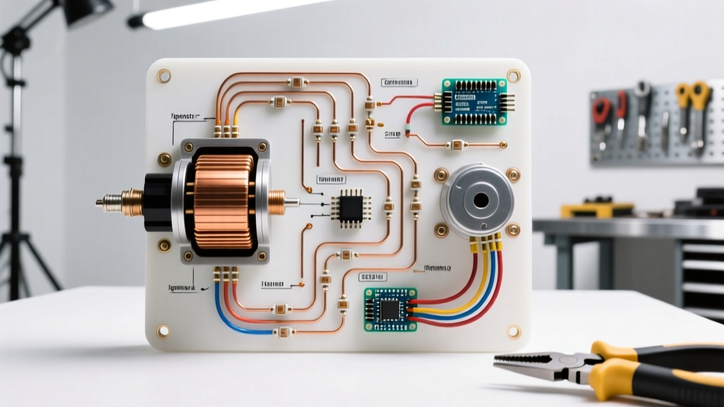
- Single-Phase Capacitor-Start Motors: Direction is determined by the phase relationship between the main (run) winding and the auxiliary (start) winding. To reverse the motor, you must swap the polarity of the start winding leads (typically labeled T5 and T8) relative to the run winding (T1 and T4).
- Three-Phase Induction Motors: The rotating magnetic field is generated by the 120-degree phase shift of the three supply lines (L1, L2, L3). Reversing the motor is as simple as swapping any two of the three incoming power lines (e.g., swapping L1 and L3).
Component Selection: Drum Switch vs. DPDT vs. Magnetic Contactor
Choosing the right switch hardware is critical. As of early 2026, pricing and availability for industrial-grade components remain stable, but selecting the wrong form factor will lead to premature contact welding. Below is a comparison matrix to guide your selection:
| Switch Type | Recommended Model (2026) | Approx. Cost | Max HP Rating | Best Application |
|---|---|---|---|---|
| Manual Drum Switch | Square D 2601-HG02 | $95 - $115 | 2 HP @ 115V / 3 HP @ 230V | Lathes, drill presses, bench grinders |
| DPDT Center-Off Toggle | Baton 11042-DEF | $18 - $25 | 1/2 HP @ 125V | Small DIY actuators, low-torque hoists |
| Magnetic Contactor (Reversing) | Eaton C25DRF330A | $210 - $260 | 3 HP @ 115V / 7.5 HP @ 230V | High-inertia loads, automated conveyors, frequent cycling |
Step-by-Step: Single-Phase Capacitor-Start Motor Wiring
For this tutorial, we will use a standard 1.5 HP, 115/230V single-phase motor (e.g., Dayton 1TDP7) and a Square D 2601-HG02 manual drum switch. This setup is the most common for home workshop machinery.
Preparation and Lead Identification
- Lockout/Tagout (LOTO): Disconnect the main breaker. Verify zero voltage at the motor terminal box using a CAT III multimeter.
- Identify Motor Leads: Open the motor peckerhead (terminal box). You will typically find 6 to 8 leads. For 115V operation, the run winding leads are usually T1, T2, T3, T4, and the start winding leads are T5 and T8. (Always verify against the manufacturer's schematic inside the terminal cover).
- Wire Gauge Selection: For a 1.5 HP motor at 115V (approx. 15A full load amps), use 12 AWG THHN copper wire. Strip exactly 3/8-inch of insulation for standard fork/spade terminals.
Drum Switch Termination Sequence
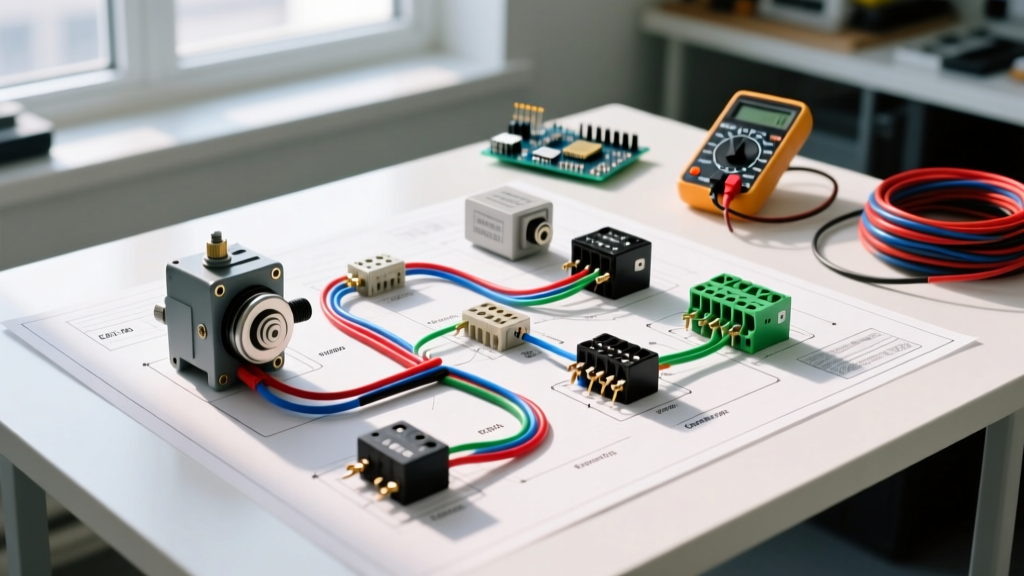
The Square D 2601-HG02 has internal crossover contacts specifically designed for forward/reverse operations. The terminals are typically labeled 1, 2, 3, 4, 5, and 6.
- Line In: Connect incoming AC Hot (L1) to Terminal 1, and Neutral (L2) to Terminal 4.
- Run Winding: Connect Motor T1 to Terminal 2, and Motor T4 to Terminal 5.
- Start Winding: Connect Motor T5 to Terminal 3, and Motor T8 to Terminal 6.
How it works: In the 'Forward' position, the switch routes L1 to T1 and L2 to T4, while simultaneously routing L1 to T5 and L2 to T8. In the 'Reverse' position, the internal cam physically swaps the start winding connections (L1 goes to T8, L2 goes to T5), reversing the magnetic phase angle and thus the rotor direction.
Step-by-Step: Three-Phase Induction Motor Wiring
Three-phase setups are vastly simpler to reverse but carry higher arc-flash risks. We will reference a Leeson C145T 3 HP, 230/460V motor controlled by a 3-position rotary cam switch.
The 'Two-Line Swap' Method
- Route incoming 3-phase power (L1, L2, L3) into the top terminals of the reversing switch.
- Wire L1 and L3 to the crossover terminals on the switch. L2 passes straight through to the motor (often labeled T2 on the switch output).
- In the 'Forward' position, the switch outputs L1->U1, L2->V1, L3->W1.
- In the 'Reverse' position, the internal contacts swap L1 and L3, outputting L3->U1, L2->V1, L1->W1.
Torque Specification: When terminating 10 AWG or 8 AWG wire into industrial cam switches or magnetic contactors, use a calibrated torque screwdriver. Most NEMA-rated contactors require between 14 to 18 in-lbs of torque. Under-torquing leads to micro-arcing and contact welding; over-torquing strips the brass threads.
Real-World Failure Modes and Troubleshooting
Even with a perfect wiring diagram for forward reverse switch implementations, environmental and mechanical factors cause failures. Here are the most common edge cases encountered in the field:
1. Motor Hums but Fails to Start in Reverse
The Cause: The start winding circuit is open. This usually happens if the centrifugal switch inside the motor is stuck, or if the external switch's T5/T8 terminals are loose.
The Fix: Use a multimeter in continuity mode to check the start winding resistance. A healthy 1.5 HP single-phase start winding typically reads between 2.5 and 4.0 ohms. If infinite, the internal thermal overload or start winding is burnt. If resistance is normal, inspect the external switch contacts for carbon buildup.
2. Contactor 'Chatter' or Welding
The Cause: If using magnetic contactors for high-inertia loads (like a heavy flywheel), the mechanical interlock between the Forward and Reverse contactors may be failing, or the control voltage is sagging during the transition.
The Fix: Ensure you are using a mechanically interlocked reversing contactor set (e.g., Schneider Electric TeSys D series). Never rely solely on electrical interlocking (auxiliary contacts) for reversing circuits, as a welded contact will cause a catastrophic phase-to-phase short circuit.
3. Plugging (Rapid Reversal) Damage
The Cause: 'Plugging' occurs when an operator slams a manual drum switch from Forward directly to Reverse while the motor is still spinning at full RPM. This induces current spikes up to 800% of the full-load amps.
The Fix: For applications requiring rapid direction changes, abandon manual drum switches. Upgrade to a Variable Frequency Drive (VFD) with dynamic braking capabilities, or install a zero-speed plugging switch that physically prevents the reverse circuit from engaging until the rotor drops below 50 RPM.
Compliance and Final Verification
Adherence to NEMA MG-1 standards ensures your motor and controller are matched for thermal endurance. Before final commissioning, verify your setup aligns with OSHA electrical safety guidelines regarding grounding and enclosure types. Ensure all ground wires (green/bare) are bonded to the motor chassis and the switch enclosure using a star washer to bite through the paint for a low-impedance fault path.
By selecting the correct switch topology, adhering to precise torque specs, and understanding the underlying magnetic physics, your forward-reverse motor control will deliver years of reliable, safe operation in any workshop or industrial environment.