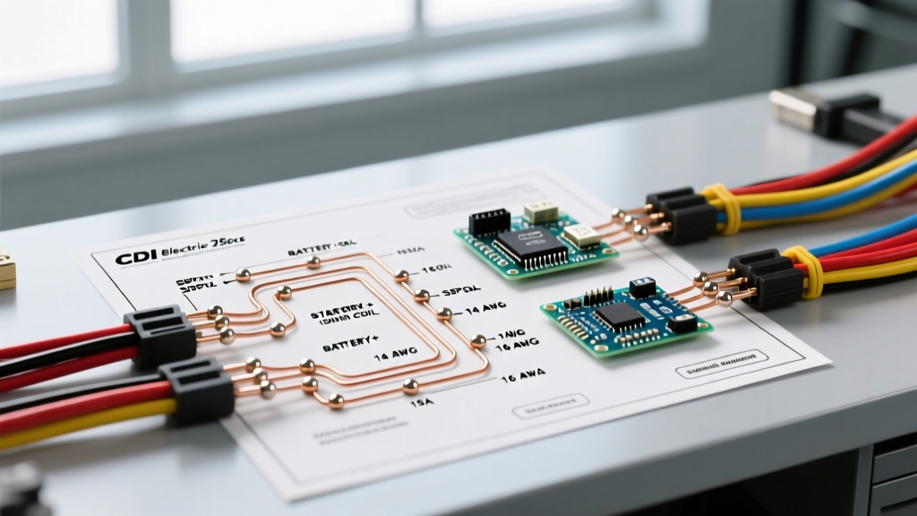

The Hidden Fire Hazards in 250cc Off-Road Electrical Systems
When modifying or repairing small displacement engines like the ubiquitous GY6 170MM, Honda XR clones, or Chinese CG250 platforms, electrical safety is frequently an afterthought. A poorly executed harness on a high-vibration vehicle is a primary catalyst for stator burnouts, voltage drops, and catastrophic chassis fires. According to the National Fire Protection Association (NFPA), electrical failures or malfunctions are leading factors in vehicle and mobile equipment fires, often stemming from improper overcurrent protection and degraded insulation.
When interpreting a standard cdi electric start 250cc wiring diagram, technicians and DIYers often overlook the environmental and mechanical stresses unique to off-road and powersport applications. This guide transcends basic wire routing, focusing strictly on safety, code compliance adaptations, and engineering best practices to ensure your 250cc platform operates reliably and safely.
Core Architecture of a Safe 250cc CDI Harness
A 250cc electric start system relies on three distinct electrical domains that must be isolated yet properly integrated:
- The High-Current Starting Circuit: Battery to starter solenoid, and solenoid to starter motor.
- The Charging & Lighting Circuit: Stator AC output to the Regulator/Rectifier (R/R), converting to DC for the battery and accessories.
- The Ignition & Logic Circuit: Pulse coil (trigger), CDI unit, ignition coil, and kill switches.
Safety Directive: Never route high-tension (HT) spark plug wires parallel to the low-voltage pulse coil or stator wires. Electromagnetic interference (EMI) from the HT wire can induce false triggers in the CDI, causing erratic timing, backfires, and potential engine damage. Maintain a minimum 2-inch separation or cross them at a strict 90-degree angle.
Wire Gauge Selection & SAE Compliance
Standard PVC-insulated wire (GPT) is inadequate for the high-heat zones near a 250cc exhaust header and the heavy vibration of a single-cylinder engine. For safety and longevity, all replacement wiring must comply with the SAE International J1128 Standard for low-tension primary cables, specifically utilizing cross-linked polyethylene (TXL or GXL) insulation, which withstands continuous temperatures up to 125°C (257°F).
| Circuit Domain | Recommended AWG | Insulation Type | Max Ampacity | Required Protection |
|---|---|---|---|---|
| Main Battery to Solenoid | 4 AWG | TXL (125°C) | 150A | 150A ANL Fuse |
| Stator to Regulator/Rectifier | 12 AWG | GXL (125°C) | 25A | 30A ATO Blade Fuse |
| CDI Main Power Feed (DC) | 16 AWG | TXL (125°C) | 10A | 5A ATO Blade Fuse |
| Ignition Coil Primary | 18 AWG | GPT (105°C) | 6A | 3A ATO Blade Fuse |
The Danger of Undersized Stator Wiring
Many factory 250cc wiring diagrams specify 14 AWG or even 16 AWG for the three yellow stator wires feeding the regulator/rectifier. Under heavy electrical load (e.g., running auxiliary LED light bars or heated grips), these wires can exceed 20 amps. The resulting resistance generates immense heat, melting standard PVC insulation and causing a short to the chassis. Upgrading to 12 AWG GXL wire mitigates this thermal runaway risk entirely.
Overcurrent Protection & Fusing Strategy
While the National Electrical Code (NEC / NFPA 70) primarily governs stationary structures, its Article 240 principles for overcurrent protection are the gold standard for designing safe mobile DC harnesses. A fuse must protect the wire, not just the component.
- Main Battery Fuse: Install a 150A ANL fuse within 6 inches of the positive battery terminal. This protects the massive 4 AWG starter cable in the event of a solenoid weld or dead short.
- Regulator/Rectifier Feed: Place a 30A ATO (Automotive Blade) fuse on the main DC output wire leaving the R/R before it enters the main harness distribution block.
- Ignition & Logic Fuses: The CDI and ignition switch should be protected by a dedicated 5A or 10A fuse. If the CDI shorts internally, a properly sized fuse will pop instantly, preventing the ignition switch from melting.
Environmental Sealing and Connector Protocols
Vibration is the enemy of electrical connections. Standard stamped spade terminals frequently back out of their housings on 250cc single-cylinder engines, leading to high-resistance arcing. Arcing in the presence of fuel vapors is a severe explosion hazard.
Mandatory Connection Standards
- Sealed Connectors: Replace all exposed spade connectors with Delphi Weather-Pack or Bosch-style sealed connector systems. These feature silicone secondary locks and weather seals that prevent moisture ingress and terminal oxidation.
- Proper Crimping: Never use pliers to crimp terminals. Use a ratcheting crimp tool (such as the IWISS IWS-3220M) calibrated for the specific terminal gauge. A proper crimp creates a cold-weld gas-tight seal that resists vibration.
- Adhesive-Lined Heat Shrink: For any inline splices, use 3:1 ratio adhesive-lined heat shrink (e.g., 3M MDR or equivalent). When heated, the inner thermoplastic adhesive melts and seals the wire strands, preventing capillary action from drawing water into the harness.
- Dielectric Grease: Apply a light coat of Nyogel 760G or standard silicone dielectric grease to the stator case connector and CDI plug to displace moisture and prevent galvanic corrosion between dissimilar metals.
Grounding: Star Topology vs. Daisy Chaining
Factory wiring diagrams often employ 'daisy chain' grounding, where the headlight grounds to the dash, the dash grounds to the frame, and the frame grounds to the engine. On a 250cc ATV or buggy, frame flex and painted mounting points create variable resistance grounds, leading to flickering lights and erratic CDI behavior.
The Safe Alternative: Implement a Star Grounding Topology. Run dedicated 12 AWG ground wires from the battery negative terminal directly to a centralized, cleaned, and bare-metal grounding bus on the engine block. From this central engine ground, route individual ground wires to the starter motor, stator housing, and ignition coil. This eliminates ground loops and ensures the CDI has a flawless reference voltage for accurate spark timing.
Fail-Safe Kill Switch Implementation
According to safety guidelines outlined by the U.S. Consumer Product Safety Commission (CPSC) for off-road vehicles, a reliable engine kill mechanism is non-negotiable. On a DC-fired CDI system, the kill switch works by interrupting the 12V power feed to the CDI. On an AC-fired system, it grounds the CDI's primary winding to the chassis to collapse the magnetic field.
Edge Case Warning: If you are installing an emergency safety tether (lanyard switch), ensure it is wired in series with the main ignition switch, not as a parallel bypass. Use a heavy-duty, IP67-rated marine toggle switch for the main kill circuit to prevent water intrusion from causing a dead battery via parasitic draw.
Troubleshooting Voltage Drop Safely
Before replacing a suspected faulty CDI or stator, perform a voltage drop test under load. With the engine cranking or running, use a digital multimeter to measure the voltage difference between the battery positive post and the CDI power input pin. A reading higher than 0.5V indicates excessive resistance in the harness, ignition switch, or emergency kill switch contacts. Addressing this resistance prevents the CDI from receiving the minimum 9.5V required to fire the ignition coil consistently at high RPMs, thereby preventing dangerous misfires on the trail.