
Why Your Food Truck Electrical Wiring Diagram is Your Best Diagnostic Tool
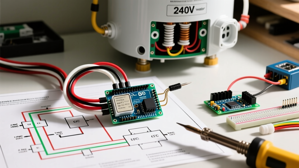
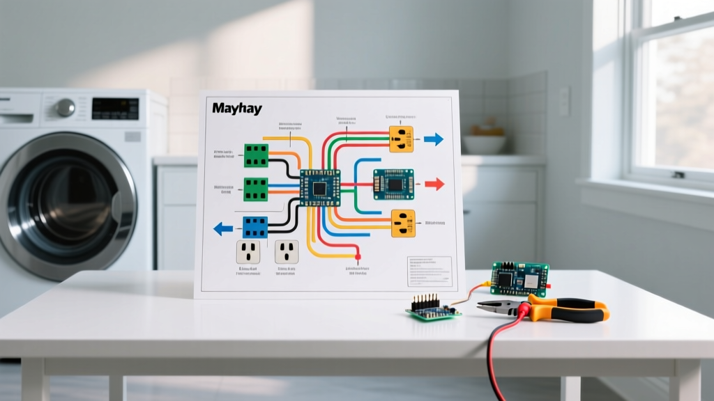
A food truck operates in one of the most punishing electrical environments imaginable. High vibration, extreme temperature fluctuations, grease accumulation, and massive simultaneous load draws from commercial kitchen equipment create a perfect storm for electrical failures. When a reach-in refrigerator stalls or a GFCI receptacle refuses to reset during a busy lunch rush, guessing is not an option. You need a systematic approach. This is where a comprehensive food truck electrical wiring diagram transitions from a mere installation blueprint to your primary diagnostic map.
In 2026, modern mobile food preparation vehicles rely heavily on complex hybrid power systems—integrating shore power, onboard generators, lithium iron phosphate (LiFePO4) battery banks, and high-capacity inverter/chargers. Tracing a fault without the schematic is like navigating a foreign city without a map. Below, we break down how to read, interpret, and actively use your wiring diagram to isolate and resolve the most common food truck electrical failures.
Decoding the 4 Core Zones of a Food Truck Schematic
Before grabbing a multimeter, you must understand how the diagram segments the electrical system. A professional-grade food truck electrical wiring diagram is typically divided into four distinct logical zones:
Zone 1: AC Input & Transfer Switching
This zone maps the 30A or 50A shore power inlet (typically a Twist-Lock L14-30R or 14-50R) and the generator input. Look for the Automatic Transfer Switch (ATS) or the internal transfer relay within the inverter/charger. The diagram will show the mechanical or solid-state interlocks that prevent shore power and generator power from back-feeding into each other—a critical safety mechanism enforced by NEC Article 551 for mobile units.
Zone 2: The Inverter/Charger Hub
The heart of the off-grid system. Diagrams here will detail the heavy-gauge DC battery cables, the AC IN/AC OUT terminals, and the communication buses (like VE.Bus or BMS CAN-bus lines). For example, a Victron MultiPlus-II 12/3000/120-50 (retailing around $1,850 in 2026) will show a specific internal neutral-ground bond relay on the schematic that is vital for troubleshooting GFCI issues.
Zone 3: AC Distribution Panel
This maps the main circuit breakers (often Blue Sea Systems C-Series or Square D QO breakers mounted in high-vibration dampened panels). The diagram traces the hot (black/red), neutral (white), and ground (green/bare) routing to individual branch circuits.
Zone 4: DC Loads & BMS Communication
Maps the 12V or 24V DC fuse blocks, LED lighting, water pumps, and the Battery Management System (BMS) communication wires that tell the inverter when to stop drawing current to prevent lithium cell depletion.
Troubleshooting 3 Common Food Truck Electrical Faults
Let’s apply the food truck electrical wiring diagram to diagnose three of the most frequent and frustrating failures encountered in mobile food service.
Fault 1: GFCI Nuisance Tripping on the Prep Counter
The Symptom: The 20A GFCI receptacle powering the commercial blender or meat slicer trips immediately when the truck switches from shore power to inverter power, but works fine when plugged into the grid.
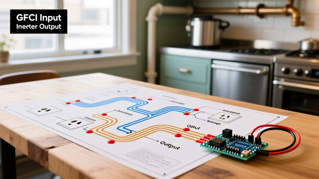
Tracing the Diagram: Look at the inverter section of your schematic. According to UL 458 standards, inverters used in mobile applications must bond the neutral and ground when operating in battery-invert mode, but must isolate them when passing through shore power. Your wiring diagram will show the internal bonding relay inside the inverter.
The Fix: If the GFCI trips only on inverter power, the bonding relay may be stuck or failing to close, causing a ground fault imbalance. Use a Fluke 117 multimeter to test continuity between the neutral bus and the ground bus at the AC distribution panel while the inverter is actively supplying power. If there is no continuity (infinite resistance), the inverter's internal relay has failed, or the external grounding diagram path is broken. Furthermore, check the diagram for any 'bootleg grounds' (neutrals tied to grounds downstream of the main panel), which will cause instantaneous trips.
Fault 2: Compressor Stalling on the Reach-In Refrigerator
The Symptom: The 1/3 HP compressor on your under-counter prep fridge hums loudly, clicks, and shuts off on thermal overload when running off the generator or inverter, but runs perfectly on shore power.
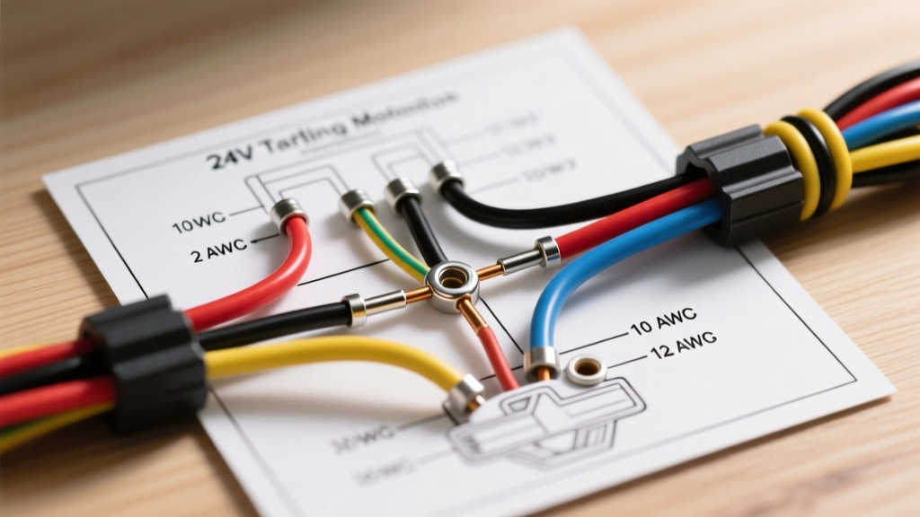
Tracing the Diagram: This is a classic voltage drop issue under heavy starting surge (LRA - Locked Rotor Amps). Follow the branch circuit on your food truck electrical wiring diagram from the breaker to the receptacle. Note the wire gauge (AWG) and the total run length specified on the schematic.
The Data: Food trucks often use marine-grade tinned copper wire (like Ancor 6 AWG at ~$2.80/ft) to resist corrosion and vibration. If the diagram shows 12 AWG wire on a 40-foot run to the fridge, the voltage drop during the compressor's 15-amp startup surge will pull the voltage below 104V, stalling the motor.
| Wire Gauge (AWG) | Running Amps (5A) | Max Run Length (One Way) | Startup Surge Tolerance (15A) |
|---|---|---|---|
| 14 AWG | 60 feet | 20 feet (Fails Compressor Start) | |
| 12 AWG | 95 feet | 31 feet (Marginal) | |
| 10 AWG | 150 feet | 50 feet (Recommended for Mobile) |
The Fix: If your diagram shows 12 AWG exceeding 30 feet for an inductive motor load, you must upgrade to 10 AWG MTW or THHN stranded wire. Always verify the terminal torque specs on the diagram; loose connections at the breaker add micro-ohms of resistance that exacerbate voltage drop.
Fault 3: Generator Auto-Start Failure During Low Battery
The Symptom: The battery bank drops to 20% State of Charge (SoC), but the onboard Honda EU7000is generator fails to auto-start via the inverter's dry contact relay.
Tracing the Diagram: Locate the 'Generator Start/Stop' DC control circuit on the schematic. This usually involves a low-voltage DC signal (often 12V or a simple dry contact closure) sent from the inverter's programmable relay to the generator's 2-pin remote start harness.
The Fix: High vibration in food trucks frequently backs out spade connectors. Use your wiring diagram to locate the exact physical terminal block on the inverter (e.g., the programmable relay terminals on the Victron Cerbo GX or MultiPlus). Set your multimeter to DC Volts. If the inverter is calling for a start, you should read 12V DC across these terminals. If you have 12V at the inverter but 0V at the generator end, you have an open circuit in the control wire—likely a severed connection behind the vibrating wall panels.
Essential Diagnostic Tools for Diagram Tracing
To effectively execute the troubleshooting steps above, your mobile toolkit must include:
- True-RMS Digital Multimeter (e.g., Fluke 117): Essential for accurate AC voltage readings on non-linear loads like variable frequency drives on commercial mixers.
- Non-Contact Voltage Tester (NCVT) with Low-Voltage Mode: Allows you to trace 12V DC thermostat or BMS wires without stripping insulation.
- Milliohm Meter: Used to verify the integrity of the chassis ground bond. The resistance between the AC ground bus and the truck's steel chassis must read less than 0.1 ohms.
- Infrared Thermometer: Scan the breaker panel while under load. A breaker reading 140°F+ indicates a loose terminal or a failing breaker internal contact, even if it hasn't tripped yet.
2026 Code Compliance & Safety Standards
When modifying or repairing a food truck based on your wiring diagram, you must adhere to current safety codes. The National Fire Protection Association (NFPA) strictly regulates mobile food units. According to NFPA 96 and NEC guidelines, all flexible wiring in a mobile food preparation vehicle must be rated for high vibration and moisture. Standard residential solid-core Romex (NM-B) is strictly prohibited because the copper will work-harden, snap, and arc under the constant vibration of driving and generator operation.
Expert Torque Warning: Never rely on 'hand-tight' for food truck electrical connections. The vibration from a commercial exhaust hood blower or driving over potholes will loosen untreated terminals within weeks. Always use a calibrated torque screwdriver. For example, Victron specifies exactly 4.0 Nm (35 in-lbs) for the AC terminal screws on a MultiPlus-II. Mark tightened screws with a Torque Seal lacquer line to visually verify during monthly inspections that vibration hasn't rotated the terminal.
For comprehensive guidelines on flexible wiring methods and vibration-resistant connectors in commercial mobile setups, always refer to the latest OSHA wiring methods standards and local health department mobile food unit checklists, which increasingly require certified electrical schematics on file during annual inspections.
Final Thoughts on Schematic Literacy
A food truck electrical wiring diagram is a living document. As you add new equipment—like a high-draw commercial espresso machine or an upgraded lithium battery bank—the diagram must be updated with red-line revisions. By mastering the ability to trace current paths, identify transfer switch logic, and calculate voltage drop directly from the schematic, you transform from a reactive equipment operator into a proactive mobile electrical technician, ensuring your kitchen never goes dark during the peak lunch rush.