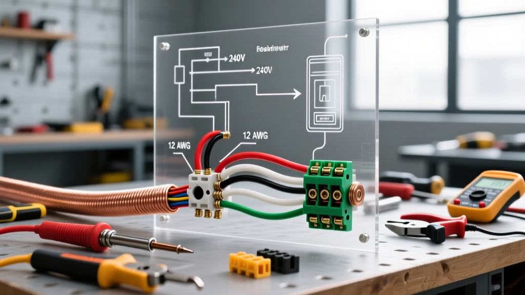

Understanding the 240V Baseboard Heater Circuit
Electric baseboard heaters remain one of the most reliable, silent, and cost-effective zone heating solutions available in 2026. Unlike forced-air systems, they have no moving parts, meaning maintenance is virtually nonexistent. However, because they rely on high-wattage electric resistance heating, the electrical demands are substantial. A standard 240-volt circuit is required for whole-room heating, and improper wiring can lead to tripped breakers, melted insulation, or severe shock hazards.
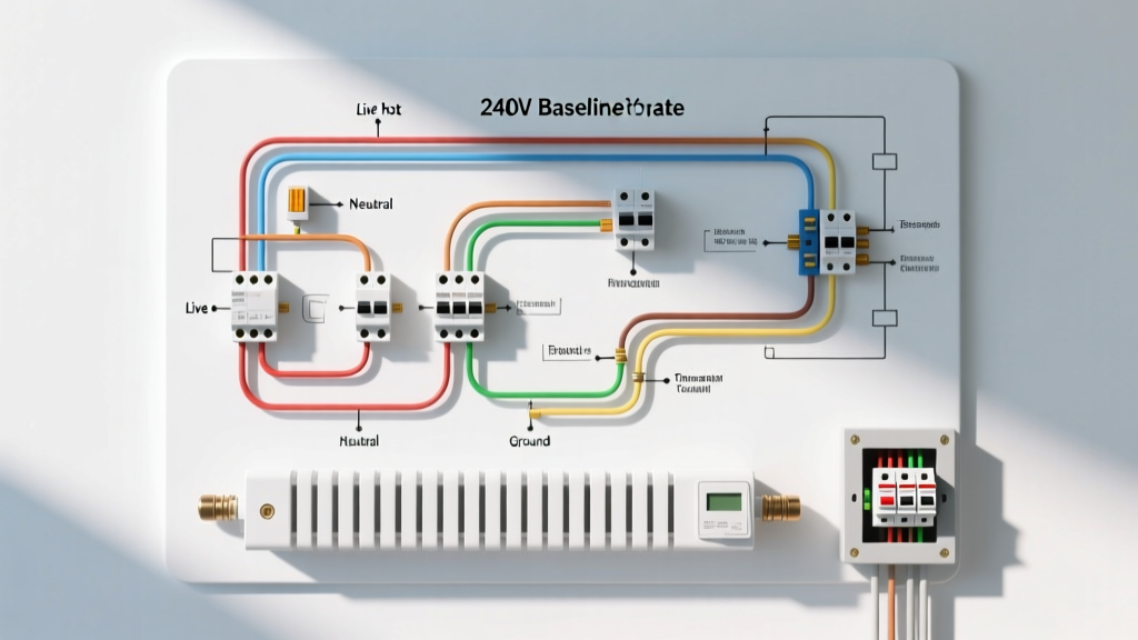
This comprehensive guide and wiring diagram for electric baseboard heater installations will walk you through the exact steps required to safely route power from your main breaker panel to a line-voltage thermostat, and finally to the heating element. Whether you are installing a single Cadet F2502W (2500W) unit or daisy-chaining multiple Marley QMark heaters in a large basement, the fundamental physics and National Electrical Code (NEC) requirements remain identical.
Pre-Wiring: Sizing, Wire Gauge, and Breaker Selection
Before pulling any wire, you must calculate the electrical load. The NEC (Article 424) classifies fixed electric space heating as a continuous load because it is expected to run for three hours or more. Therefore, the circuit must be sized at 125% of the heater's maximum amperage.
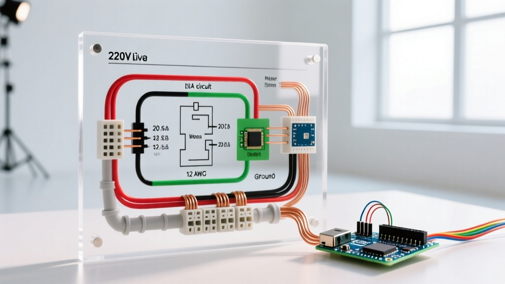
For example, a 2000W heater at 240V draws 8.33 Amps. Multiplying by 1.25 gives 10.41 Amps. While a 15-Amp breaker could technically handle this, standard industry practice in 2026 dictates using 12 AWG wire on a 20-Amp double-pole breaker to minimize voltage drop and provide headroom for future upgrades.
Wire Gauge and Breaker Sizing Matrix
| Total Heater Wattage (240V) | Actual Amps | 125% Continuous Load | Min. Wire Gauge (Copper) | Double-Pole Breaker |
|---|---|---|---|---|
| Up to 1920W | 8.0A | 10.0A | 14 AWG (12 AWG Rec.) | 15A or 20A |
| 1921W - 3840W | 8.1A - 16.0A | 10.1A - 20.0A | 12 AWG NM-B | 20A |
| 3841W - 5760W | 16.1A - 24.0A | 20.1A - 30.0A | 10 AWG NM-B | 30A |
The Core Wiring Diagram: Panel to Thermostat to Heater
Visualizing the circuit path is essential. In a standard 240V setup using 12/2 NM-B (Romex) cable, you have a Black wire (Line 1), a White wire (Line 2), and a Bare Copper wire (Ground). There is no neutral wire in a standard 240V baseboard circuit.
The White Wire Re-Identification Rule
Because 12/2 cable includes a white wire, the NEC requires you to re-identify this wire as a hot conductor. You must wrap the white wire with black or red electrical tape (or use a permanent marker) at both the panel end and the thermostat/heater end. This signals to future electricians that the white wire is carrying 120V to 240V, not serving as a grounded neutral.
Smart Thermostat Exception (12/3 NM-B Required)
If you plan to install a modern smart thermostat in 2026—such as the Sinopé TH1123ZB-G2-U (which supports Matter/Thread protocols for smart home integration)—the device requires a continuous 120V power supply to keep its internal Wi-Fi/Zigbee radio alive. This means you must run 12/3 NM-B cable (Black, Red, White, Bare) from the panel to the thermostat to provide both 240V for the heater and a dedicated 120V neutral for the smart screen.
Step-by-Step Physical Wiring Walkthrough
- Run the Cable: Feed your 12/2 NM-B cable from the main breaker panel through the wall cavities to the thermostat junction box, and then down to the heater junction box. Leave at least 8 inches of slack in each box.
- Panel Connections: Connect the bare copper to the ground bus bar. Connect the black wire to one pole of the 20A double-pole breaker, and the taped white wire to the other pole. Snap the breaker into the panel (do not turn it on yet).
- Thermostat Connections (Line Side): At the thermostat box, connect the incoming bare ground to the green ground screw. Connect the incoming black wire to the thermostat terminal labeled L1 (or Line 1). Connect the incoming taped white wire to L2 (or Line 2).
- Thermostat Connections (Load Side): Connect the outgoing black wire (heading to the heater) to the terminal labeled T1 (or Load 1). Connect the outgoing taped white wire to T2 (or Load 2).
- Heater Connections: At the baseboard heater junction box, connect the bare ground to the heater's grounding pigtail. Connect the black wire to the heater's L1 terminal and the white wire to the L2 terminal. (Note: Baseboard heating elements are non-polarized; swapping L1 and L2 at the heater will not affect performance).
- Secure and Test: Tuck the wires neatly, secure the thermostat and heater to the wall boxes, turn on the breaker, and set the thermostat to call for heat.
Daisy-Chaining Multiple Heaters in Parallel
If you are heating a large room, you may need to wire multiple baseboard heaters to a single thermostat. Heaters must always be wired in parallel, never in series. Wiring in series divides the voltage, causing the heaters to output a fraction of their rated BTU and potentially damaging the elements.
To daisy-chain in parallel, run a separate 12/2 NM-B cable from the first heater's junction box to the second heater's junction box. Connect Black to Black, White to White, and Ground to Ground using appropriate wire nuts or Wago lever connectors. The thermostat will now act as a single switch controlling the entire parallel circuit. Just ensure the combined wattage of all heaters on the circuit does not exceed 3840W (the 80% continuous load limit for a 20A breaker).
Real-World Troubleshooting & Edge Cases
Even with a perfect wiring diagram for electric baseboard heater setups, field conditions can cause issues. Here are the most common failure modes we see in the field:
- Thermal Limit Switch Tripping: Baseboard heaters rely on natural convection. If furniture, heavy drapes, or thick carpeting blocks the bottom intake or top exhaust, the internal temperature spikes. The heater's built-in high-limit safety switch will trip, cutting power. Fix: Maintain a minimum 6-inch clearance in front of and above the heater.
- Single-Pole Thermostat on 240V Circuit: Using a single-pole line-voltage thermostat only breaks one leg (L1) of the 240V circuit. The heater will turn off, but 120V still flows through the heating element to the open switch. This is a severe shock hazard during maintenance and violates NEC 424.20(A). Fix: Always use a double-pole thermostat for 240V heaters, which breaks both hot legs simultaneously.
- Clicking Thermostat but No Heat: If you hear the thermostat relay click but the heater remains cold, the high-limit switch inside the heater has likely tripped due to dust buildup on the fins. Fix: Turn off the breaker, remove the heater covers, and use compressed air or a soft brush to clean the aluminum fins.
Expert Insight: 'With copper prices remaining volatile through 2026, some DIYers attempt to save money by using 14 AWG wire on 20A circuits or overloading a single 20A circuit with 4500W of heating elements. This is a fire hazard. The continuous load rule is not a suggestion; it is a mathematical necessity to prevent thermal degradation of wire insulation over time.'
Authoritative References & Further Reading
To ensure your installation meets local codes and safety standards, consult the following resources:
- National Fire Protection Association (NFPA) - Reference NEC Article 424 (Fixed Electric Space-Heating Equipment) and Article 240 (Overcurrent Protection) for continuous load calculations.
- U.S. Department of Energy (Energy.gov) - Comprehensive data on electric resistance heating efficiency, zone heating strategies, and energy cost comparisons.
- Cadet Heat Installation Guides - Manufacturer-specific wiring diagrams, clearance requirements, and troubleshooting for industry-standard baseboard models.