
The Intersection of RV Solar and High-Draw Motor Loads
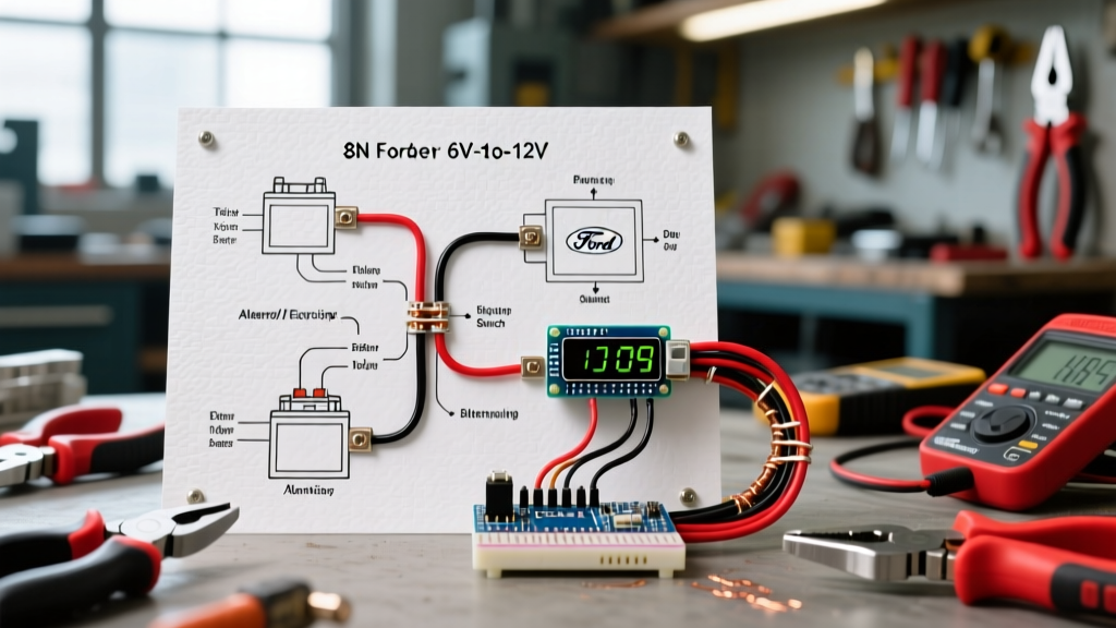
Designing a reliable off-grid electrical system for a recreational vehicle requires much more than simply mounting photovoltaic panels on the roof and connecting them to a battery. When you introduce high-draw inductive loads—such as 12V DC water pumps, slide-out motors, roof vent fans, and inverter-driven AC compressor fridges—your wiring architecture must be engineered to handle massive inrush currents without triggering low-voltage disconnects or causing dangerous voltage sag. This comprehensive tutorial dissects the ultimate solar wiring diagram for RV applications, with a specialized focus on safely routing power to demanding DC and AC motor loads.
As of 2026, the standard for RV solar has shifted heavily toward Lithium Iron Phosphate (LiFePO4) batteries and high-efficiency MPPT charge controllers. However, the physics of electric motors remain unchanged. DC motors require a significant surge of current to overcome initial inertia (inrush current), which can be two to four times their continuous running amperage. If your wire gauge is undersized or your busbar connections are loose, the resulting voltage drop will force the motor to draw even more current to compensate, leading to overheated windings, melted insulation, and tripped Battery Management System (BMS) safeguards.
Core System Components and 2026 Pricing Benchmarks
Before mapping out the wiring diagram, it is critical to select components that can handle the specific electrical characteristics of motor loads. Below is a benchmark of premium, marine-grade components commonly used in high-end RV solar builds:
- Solar Charge Controller: Victron SmartSolar MPPT 150/35 (Approx. $260). Capable of handling up to 2000W of solar at 12V, featuring rapid tracking essential for partial shading on RV roofs.
- Battery Bank: Battle Born 100Ah LiFePO4 (Approx. $899 per unit). Features an internal BMS capable of sustaining 100A continuous draw and 200A surge for 30 seconds—critical for motor startup.
- Inverter: Samlex 2000W Pure Sine Wave (Approx. $450). Pure sine wave output is non-negotiable for AC motor loads like roof air conditioners or residential fridge compressors, preventing motor hum and overheating.
- Distribution: Blue Sea Systems 250A BusBars with insulating covers (Approx. $45). Essential for centralizing high-current connections and minimizing resistance.
Sizing Wire Gauges for Inductive Motor Loads
The most common point of failure in RV motor wiring is voltage drop. According to the National Electrical Code (NFPA 70), voltage drop for branch circuits should ideally be limited to 3% to ensure equipment operates efficiently. For DC motors, a drop below 11.5V on a 12V nominal system can cause severe performance degradation.
| Motor / Appliance Type | Continuous Amps | Inrush Surge | Min Wire Gauge (15ft Run) | Recommended Fuse |
|---|---|---|---|---|
| Shurflo 4008 Water Pump | 7.0A | 15.0A | 12 AWG Stranded | 15A Blade |
| Dometic 12V Compressor Fridge | 6.0A | 12.0A | 12 AWG Stranded | 15A Blade |
| RV Slide-Out Motor (Typical) | 15.0A | 35.0A | 8 AWG Stranded | 40A ANL |
| Maxxair Roof Vent Fan | 3.0A | 5.0A | 14 AWG Stranded | 10A Blade |
| Inverter (2000W) feeding AC Motors | 160.0A | 300.0A | 2/0 AWG Pure Copper | 250A Class T |
Note: Always use marine-grade, tinned copper stranded wire (like Ancor or WindyNation) rather than solid core THHN. RVs experience constant vibration, which will snap solid core wire and cause hidden arcing faults.
Step-by-Step Solar Wiring Diagram Execution
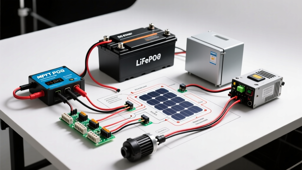
Executing a safe and efficient solar wiring diagram for an RV requires a strict sequencing protocol. Never connect the solar panels to the charge controller before the battery is connected; doing so can instantly destroy the MPPT controller's internal logic board.
Phase 1: The DC Charging Circuit
Begin by wiring the battery bank to the MPPT charge controller. Use 6 AWG stranded copper wire for runs under 10 feet, and 4 AWG for longer runs. Install a 60A Bussmann circuit breaker or a 60A MIDI fuse on the positive wire, positioned within 7 inches of the battery positive terminal. This protects the wiring from short circuits and allows you to manually disconnect the solar charging source for maintenance.
Next, route the PV (photovoltaic) wires from the roof down through a marine-grade cable gland. Connect these to a DC disconnect switch or a PV breaker mounted near the ceiling, then run them down to the MPPT controller's solar input terminals. Ensure your panels are wired in series to increase voltage (e.g., two 200W panels in series yielding ~40V), which allows the MPPT controller to operate more efficiently and use smaller gauge wire (10 AWG) for the roof-to-controller run.
Phase 2: The High-Current Inversion Circuit
The inverter is the heart of your AC motor power supply. Because a 2000W inverter can pull upwards of 180A continuously from a 12V battery bank, the wiring must be massive. Use 2/0 AWG (zero-zero) pure copper stranded wire. Keep the physical distance between the battery busbars and the inverter as short as possible—ideally under 5 feet.
Install a 250A Class T fuse on the main positive inverter cable. Class T fuses are specifically designed to handle the extreme inrush currents and high interrupt capacity required by large inverter banks, unlike standard ANL fuses which can nuisance-blow during heavy AC motor startups. As detailed in the authoritative Victron Energy Wiring Unlimited Guide, proper torquing of these heavy lugs to the manufacturer's specification (usually around 10-12 Nm) is mandatory to prevent thermal runaway at the connection point.
Phase 3: DC Motor Load Distribution
For native 12V DC motors like water pumps and slide-outs, do not wire them directly to the battery terminals. Instead, route power from the main battery busbars to a dedicated DC fuse block (such as the Blue Sea Systems ST Blade). Use 8 AWG wire to feed the fuse block, protected by an 80A master breaker. From the fuse block, run individual 12 AWG or 14 AWG wires to each specific motor load, utilizing appropriately sized blade fuses.
For slide-out motors, which draw heavy current and are often located far from the main battery bank, consider installing a localized secondary busbar or a dedicated heavy-duty relay to minimize voltage drop across the length of the chassis.
Troubleshooting Motor Hum and Voltage Sag
Even with a perfect solar wiring diagram, RVers frequently encounter issues when high-draw motors engage. Here is how to diagnose the most common motor-related electrical faults:
- The 'Click-Click' Water Pump: If your Shurflo water pump rapidly cycles on and off or clicks without pumping, you likely have severe voltage drop. The motor starts, the voltage at the pump drops below the pressure switch's threshold, the switch opens, voltage recovers, and the switch closes again. Upsize the wiring from 14 AWG to 10 AWG and check for corroded crimp connectors.
- Inverter Low-Voltage Alarm on AC Motor Startup: When starting a roof AC compressor via the inverter, the BMS may cut power due to a momentary voltage sag. This occurs if the battery bank is too small or the interconnecting cables are too thin. Upgrading from a single 100Ah battery to a parallel 200Ah or 300Ah configuration drastically reduces internal resistance and stabilizes voltage during inductive surges.
- Slide-Out Motor Stalling: If a slide-out motor stalls halfway through its travel, check the grounding path. Many RV manufacturers use the metal chassis as a ground return for slide-out motors. Over time, rust and paint interfere with this ground. Run a dedicated 8 AWG negative ground wire directly from the motor's negative terminal back to the main negative busbar.
Expert Insight: Never rely on the battery's internal BMS as your primary overcurrent protection for motor loads. The BMS is a safety device of last resort. Always use properly sized external fuses and breakers to protect the wiring. If a motor seizes and draws locked-rotor amperage, the external fuse must blow before the wire insulation melts or the BMS permanently damages its internal MOSFETs.
Final System Validation and Safety Checks
Once all wiring is complete, perform a systematic validation before energizing the system. Use a digital multimeter to verify the open-circuit voltage (Voc) of your solar array before connecting it to the MPPT controller, ensuring it does not exceed the controller's maximum input rating (e.g., 150V for the Victron 150/35). According to the U.S. Department of Energy Solar Guide, proper system commissioning and polarity checks are vital for long-term equipment survival.
Turn on the inverter and measure the AC output voltage; it should read a clean 115V to 120V. Engage your DC motor loads one by one, monitoring the battery voltage at the busbars. A healthy LiFePO4 bank should not sag below 12.8V under normal continuous motor loads. By adhering to this rigorous solar wiring diagram methodology, you ensure your RV's motors operate smoothly, safely, and efficiently for years of off-grid exploration.