
The Critical Link Between Wiring Diagrams and Physical Wire Specs
When you unroll a residential electrical wiring diagram, you are looking at a schematic blueprint that dictates the safety, efficiency, and code compliance of your home's electrical system. However, a common point of failure for DIYers and junior electricians is the inability to translate the abstract lines and labels on a diagram into the physical wire gauge and color codes required by the National Electrical Code (NEC). As jurisdictions continue to adopt the 2023 and upcoming 2026 NEC cycles, understanding the precise relationship between diagram notations, American Wire Gauge (AWG) sizing, and insulation color coding is non-negotiable.
This guide bridges the gap between schematic design and physical installation, providing a deep-dive reference into wire gauges, color codes, and ampacity limits essential for executing any residential wiring project safely.
Decoding Colors: Outer Jacket vs. Inner Conductors
A frequent mistake when reading a residential electrical wiring diagram is confusing the color of the wire's outer jacket with the color of the individual inner conductors. Non-metallic sheathed cable (commonly known by the brand name Romex or NM-B) uses outer jacket colors to quickly indicate the wire gauge to inspectors and electricians on the job site.
Outer Jacket Color Code (NM-B Cable)
Manufacturers like Southwire and Cerrowire adhere to a standardized color-coding system for the outer PVC jacket of NM-B cables. When a diagram specifies a gauge, you should immediately know which jacket color to pull from the supply house.
| Outer Jacket Color | Wire Gauge (AWG) | Primary Residential Application |
|---|---|---|
| White | 14 AWG | 15-Amp lighting circuits and standard receptacles |
| Yellow | 12 AWG | 20-Amp small appliance, bathroom, and outdoor receptacles |
| Orange | 10 AWG | 30-Amp water heaters and heavy-duty tool circuits |
| Black | 8 AWG and larger | 40-Amp to 60-Amp ranges, EV chargers, and subpanels |
Inner Conductor Color Code
Once you strip the outer jacket, the individual conductors follow a strict NEC color code (NEC 200.6, 210.5, and 250.119). A residential electrical wiring diagram will use these colors to denote the function of each line.
- Black: Primary 'Hot' conductor. Carries 120V from the breaker to the load.
- Red: Secondary 'Hot' conductor. Used in 240V circuits, 3-way/4-way switch travelers, and Multi-Wire Branch Circuits (MWBC).
- Blue/Yellow: Additional hot conductors, typically found in 12/4 or 10/4 cables for complex switching or specific appliance controls.
- White (or Gray): Grounded 'Neutral' conductor. Completes the circuit back to the panel. Note: White can be used as a hot conductor if re-identified with black tape, a common practice in switch loops.
- Bare Copper or Green: Equipment Grounding Conductor (EGC). Provides a safe path for fault currents.
Wire Gauge Sizing and NEC Ampacity Limits
Wire gauge refers to the physical diameter of the conductive metal. In the AWG system, the relationship is inverse: a smaller number means a thicker wire with higher current-carrying capacity (ampacity). When a residential electrical wiring diagram calls for a specific circuit, the breaker size and wire gauge must be perfectly matched to prevent thermal overload and fire.
Ampacity and Breaker Matching Matrix
According to NFPA's National Electrical Code (specifically Article 240.4), overcurrent protection devices (breakers) must be sized to protect the wire, not just the appliance. Below is the definitive reference for copper conductors in standard residential NM-B cable (rated for 60°C/90°C termination limits).
| Wire Gauge (AWG) | Max Breaker Size | Max Continuous Load (80% Rule) | Max Wattage (120V / 240V) |
|---|---|---|---|
| 14 AWG | 15 Amps | 12 Amps | 1,440W / 2,880W |
| 12 AWG | 20 Amps | 16 Amps | 1,920W / 3,840W |
| 10 AWG | 30 Amps | 24 Amps | 2,880W / 5,760W |
| 8 AWG | 40 Amps | 32 Amps | 3,840W / 7,680W |
| 6 AWG | 55 Amps (Usually 60A) | 44 Amps | 5,280W / 10,560W |
The 125% Continuous Load Rule: NEC Article 210.20(A) mandates that if a load is expected to run for 3 hours or more (like an EV charger or baseboard heater), the circuit must be derated to 80% of its capacity. A 20-Amp circuit on 12 AWG wire can only safely handle a 16-Amp continuous load.
Translating Diagram Labels to Physical Wire Specs
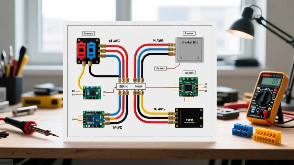
On a professional residential electrical wiring diagram, you will rarely see the words 'Yellow Romex.' Instead, you will see technical shorthand. Learning to read this shorthand is crucial for accurate material estimation and code compliance.
Common Diagram Notations Explained
- 12/2 NM-B w/ Grnd: This indicates a 12 AWG cable containing two current-carrying conductors (one black hot, one white neutral) plus a bare ground wire. Used for 20A standard receptacles.
- 14/3 NM-B w/ Grnd: A 14 AWG cable with three current-carrying conductors (black, red, white) plus ground. Typically used for 3-way light switches or split-wired duplex receptacles on 15A circuits.
- 10/3 NM-B: A 10 AWG cable with black, red, white, and ground. The standard for 120/240V appliances like standard electric dryers (30A) requiring two hot legs and a neutral.
Pro-Tip: The number before the slash dictates the gauge, while the number after the slash dictates the count of insulated conductors. The bare ground wire is never counted in this numbering scheme.
Specialized Circuits: MWBC and 240V Appliances
Advanced residential electrical wiring diagrams often incorporate Multi-Wire Branch Circuits (MWBC) to save wire and panel space. An MWBC uses a 3-wire cable (like 12/3 NM-B) to feed two separate 120V circuits that share a single neutral wire. The black and red wires are connected to a double-pole 20A breaker, ensuring they are on opposite phases (legs) of the panel. This causes the neutral current to cancel out rather than stack.
Crucial MWBC Safety Requirements
If your diagram specifies an MWBC, NEC 210.4(B) requires a simultaneous disconnect mechanism. You must use a double-pole breaker or install an approved handle tie on two adjacent single-pole breakers. Failing to do this can result in a lethal shock hazard if an electrician turns off one breaker to work on the circuit, unaware that the shared neutral is still carrying return current from the active second leg.
Voltage Drop and Long-Run Adjustments
While standard ampacity tables assume standard run lengths, a high-quality residential electrical wiring diagram will account for voltage drop on long runs. NEC 310.14 provides guidelines, and industry best practices recommend keeping voltage drop under 3% for branch circuits and 5% for the combined feeder and branch.
If a diagram shows a 12 AWG wire running 150 feet to a detached garage receptacle, the physical resistance of the copper will cause a significant voltage drop, potentially damaging power tools or electronics. In these scenarios, the diagram should specify upsizing to 10 AWG or even 8 AWG wire, despite the load only requiring a 20-Amp breaker. Always calculate voltage drop using the formula: VD = (2 x L x R x I) / 1000, where L is one-way length, R is wire resistance per 1000ft, and I is current.
Common Mistakes to Avoid During Installation
- Mixing Aluminum and Copper: Older homes or specific service entrance cables may use aluminum. Never directly connect aluminum to copper wire using standard wire nuts. This causes galvanic corrosion, leading to high resistance, arcing, and fires. Use only CO/ALR rated devices or specialized lug connectors like the AlumiConn.
- Undersizing Ground Wires: When upsizing hot and neutral wires for voltage drop, the equipment grounding conductor must also be increased proportionally per NEC 250.122(B).
- Ignoring Temperature Ratings: While NM-B wire insulation is rated for 90°C, the termination points (breakers and receptacles) in residential panels are almost universally rated for 60°C or 75°C. You must size your breaker based on the 60°C/75°C ampacity column in NEC Table 310.16, not the 90°C column.
By meticulously cross-referencing your residential electrical wiring diagram with these physical wire gauge and color code standards, you ensure that your installation is not only functional but fundamentally safe and fully compliant with modern electrical codes.