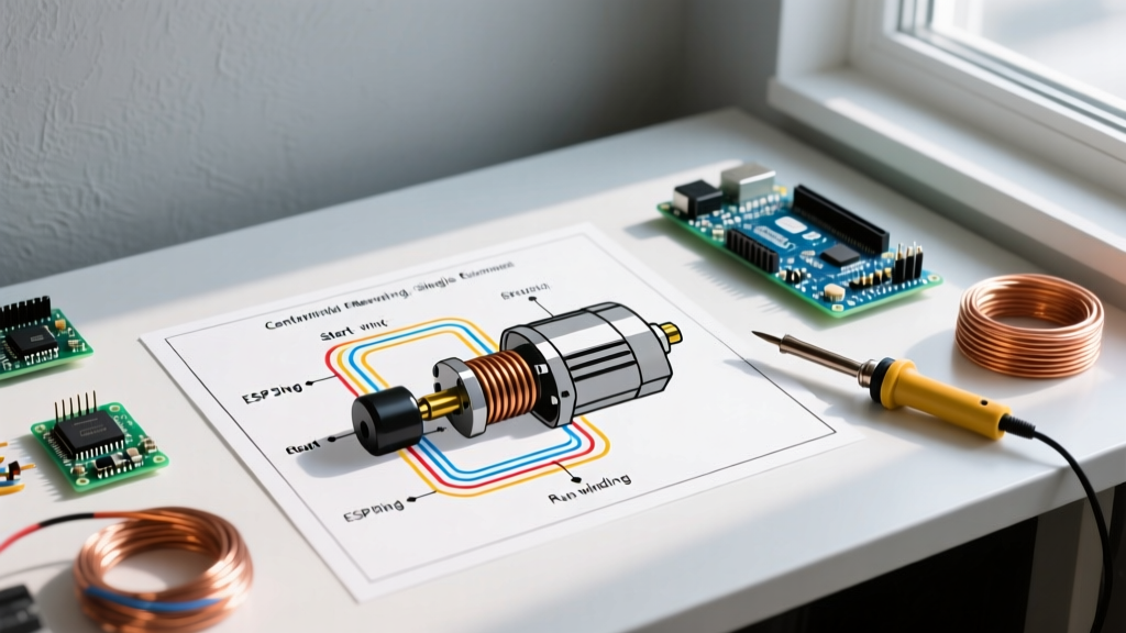

The Anatomy of Single-Phase Motor Reversal
Reversing a single-phase AC motor is fundamentally different from swapping two leads on a three-phase motor. In a three-phase system, swapping any two power legs reverses the rotating magnetic field. Single-phase motors, however, rely on a phase shift created by a start winding and a capacitor to generate starting torque. To reverse the direction of rotation, you must reverse the polarity of the start winding relative to the run winding. This is where a precise wiring diagram for reversing single phase motor circuits becomes critical.
Most industrial single-phase motors (like the Leeson C145T17GK55 or WEG CW/CCW 1 HP models) follow the NEMA MG-1 standard for lead designations. The run winding typically utilizes leads T1, T2, T3, and T4, while the start winding uses T5, T6, T7, and T8. Reversing the motor requires swapping the connection of the start winding leads (usually T5 and T8) across the AC line, while the run winding (T1 and T4) remains static.
Decoding the Wiring Diagram for Reversing Single Phase Motor
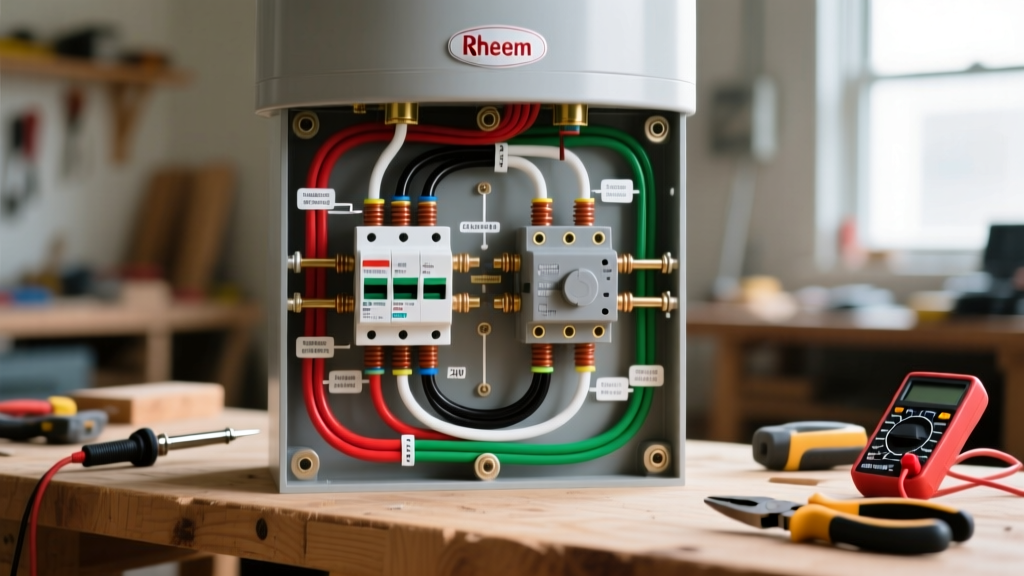
When you look at a standard reversing diagram, you will typically see a Drum Switch (such as the Dayton 2X442 or Furnas R10-303) integrated into the circuit. These switches are Double-Pole, Double-Throw (DPDT) devices specifically designed to handle the high inrush currents of motor starting—often rated for 30A at 240VAC.
Drum Switch Terminal Mapping
A common point of failure and confusion is misinterpreting the drum switch terminal block. The Dayton 2X442, which retails for approximately $55 to $70, features six main terminals plus ground:
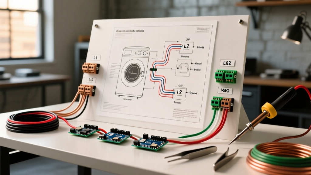
- L1 and L2: Incoming AC power lines (Hot and Neutral, or Hot and Hot for 240V).
- T1 and T2: Outgoing power to the motor's run winding.
- T3 and T4: Outgoing power to the motor's start winding (via the centrifugal switch and start capacitor).
In the 'Forward' position, L1 connects to T1 and T3, while L2 connects to T2 and T4. When you throw the lever to 'Reverse', the internal cam rotates, crossing the start winding connections so that L1 connects to T1 and T4, and L2 connects to T2 and T3. This swaps the start winding polarity, reversing the phase angle and the motor's rotation.
Troubleshooting Matrix: Symptoms, Diagram Checks, and Fixes
When a motor fails to reverse, hums, or trips the breaker, technicians often replace the motor prematurely. Use this diagnostic matrix alongside your wiring diagram to isolate the fault accurately. Always use a True-RMS multimeter, such as the Fluke 87V, for accurate impedance and voltage readings.
| Symptom | Diagram Check Point | Probable Cause | Actionable Fix |
|---|---|---|---|
| Motor hums loudly in Reverse, but runs fine in Forward. | Start Winding Circuit (T5-T8 path through drum switch) | Open circuit in the drum switch reverse cam, or broken start winding wire. | Check continuity across drum switch T3 and T4 in the Reverse position. If open, replace switch. If closed, test motor start winding resistance (expect 4-10 ohms). |
| Motor runs in one direction regardless of switch position. | Start Winding Polarity Swap (T3/T4 crossover) | Drum switch internal contacts welded together or wired incorrectly (start and run windings tied in parallel). | Verify T3 and T4 are strictly on the start winding. Ensure the run winding is fed directly or through the non-swapped poles of the switch. |
| Breaker trips instantly when switching from Forward to Reverse while running. | Centrifugal Switch & Capacitor Path | Plugging (reversing while running). The centrifugal switch hasn't re-engaged, causing a dead short or massive inrush current. | Install a zero-speed switch or enforce a mandatory 'Stop' and 2-second delay before engaging 'Reverse' to allow the motor to coast down and the centrifugal switch to reset. |
| Motor reverses but lacks torque and stalls under load. | Start Capacitor (Usually 108-130 µF for 1HP motors) | Weak or open start capacitor in the reverse circuit path. | Discharge capacitor with a 20kΩ 5W resistor. Test capacitance with a Fluke 87V. Replace if reading is below 90% of the microfarad rating. |
Edge Cases: When the Diagram Doesn't Match the Motor
One of the most frustrating scenarios in the field is encountering a motor with non-standard lead markings or a 3-lead start winding. According to the NEMA MG-1 standards for motors and generators, while T-leads are standardized, older or imported fractional-horsepower motors may use color-coded wires (e.g., Black, Red, Yellow, White) instead of numbered tags.
Identifying Unmarked Windings
If you are troubleshooting an unmarked motor, you must map the windings manually before applying power:
- Isolate all leads: Disconnect all motor wires from the power source and each other.
- Find the pairs: Use your multimeter in continuity mode to find which wires belong together. You should identify two distinct circuits (Run and Start).
- Measure resistance: Switch to the lowest Ohms setting. The Run winding will have a very low resistance (typically 0.5Ω to 2.0Ω for a 1 HP motor). The Start winding will have a higher resistance (typically 3.0Ω to 12.0Ω) because it uses thinner gauge wire with more turns to create the necessary phase shift impedance.
- Mark the leads: Tag the low-resistance pair as Run (T1/T4) and the high-resistance pair as Start (T5/T8).
Testing the Centrifugal Switch: The Hidden Culprit
The centrifugal switch is a mechanical device mounted on the rear shaft inside the motor bell housing. Its job is to disconnect the start winding and capacitor once the motor reaches roughly 75% of its rated RPM (around 1300 RPM for a 1725 RPM motor). If you are using a wiring diagram for reversing single phase motor setups and the motor refuses to start in one direction, the centrifugal switch is the prime suspect.
Expert Tip: Never attempt to test a start capacitor or centrifugal switch without first locking out the power and physically discharging the capacitor. A charged 130µF start capacitor at 240V can deliver a lethal shock or destroy your multimeter's fuse if tested in voltage mode.
To test the switch, remove the rear bell housing. With the motor at rest, the switch contacts should be closed. Push the movable contact plate inward with your finger to simulate the motor reaching operating speed; the contacts should snap open. If the contacts are pitted, burnt, or stuck open, the start winding will never engage, and the motor will simply hum and draw locked-rotor amperage (LRA) until the thermal overload trips. For detailed diagnostic procedures on single-phase motor components, the Electrical Engineering Portal's guide on single-phase motor troubleshooting provides excellent oscilloscope and multimeter waveform references.
Thermal Overload and Protection Coordination
When troubleshooting reversing circuits, always verify the thermal overload heater sizing. Reversing a motor causes a secondary inrush current event. If the motor is reversed frequently (jogging or inching), the standard thermal overload may nuisance-trip due to heat accumulation. In these applications, the wiring diagram must include a Class 10 or Class 20 solid-state motor protection relay (like the Eaton C441) rather than a traditional bimetallic strip overload. Solid-state relays can be programmed to account for the thermal capacity of the motor during rapid start-stop-reverse cycles, preventing false trips while still protecting the windings from burning out.
Safety and Compliance Notes
All reversing motor installations must comply with NEC Article 430, specifically Part C (Motor Overload Protection) and Part D (Motor Control Circuits). Ensure that the drum switch or magnetic contactor setup includes mechanical or electrical interlocks to prevent the Forward and Reverse contactors from engaging simultaneously, which would result in a catastrophic phase-to-phase short circuit. Always perform Lockout/Tagout (LOTO) procedures before opening any peckerhead (conduit box) or drum switch enclosure.