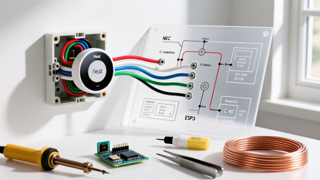

Mastering the Nest Thermostat Wiring Diagram for Heat Pump Systems
Upgrading to a smart thermostat is one of the most effective ways to optimize your home's HVAC efficiency, but heat pump systems introduce unique wiring complexities that standard gas furnace setups do not. According to ENERGY STAR Heat Pump Guidelines, modern heat pumps can reduce electricity use for heating by approximately 50% compared to electric resistance heating, provided the thermostat controls the reversing valve and auxiliary heat strips correctly. In 2026, the Google Nest Learning Thermostat (4th Gen) remains the gold standard for these setups, retailing around $279, but its advanced features rely entirely on precise terminal wiring.
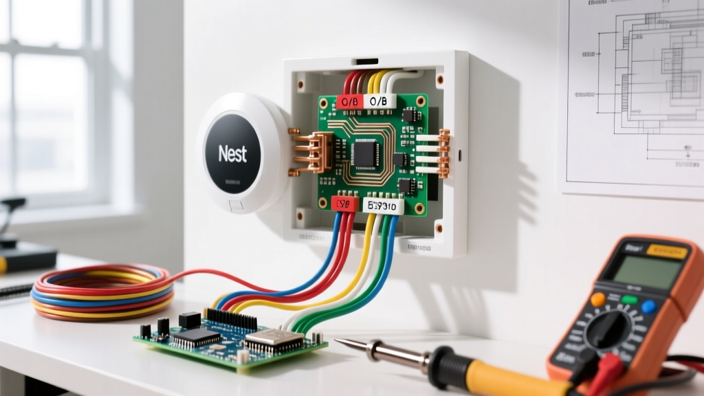
This comprehensive, step-by-step walkthrough will guide you through the exact Nest thermostat wiring diagram for heat pump configurations. We will cover critical edge cases like the O/B reversing valve dilemma, dual-fuel fossil fuel kits, and C-wire power stealing prevention, ensuring your system operates safely and efficiently in accordance with National Electrical Code (NEC) Article 440 standards for air-conditioning and refrigerating equipment.
Pre-Wiring Safety and System Identification
Before touching a single wire, you must eliminate the risk of electrical shock and protect your HVAC control board from short circuits. A blown 3-amp or 5-amp automotive-style fuse on your air handler's control board is the most common mistake DIYers make during thermostat swaps.
- Shut Off Power: Turn off the dedicated 240V double-pole breaker for the outdoor heat pump condenser and the 120V breaker for the indoor air handler/furnace at your main electrical panel.
- Verify Zero Voltage: Use a non-contact voltage tester or a multimeter set to AC voltage to confirm no power is present at the old thermostat's R (power) and C (common) wires.
- Document the Old Wiring: Take a high-resolution photo of your existing thermostat's wiring. Do not rely on memory or the color of the wires, as previous installers frequently deviate from standard 18/5 or 18/8 thermostat wire color codes.
Pro-Tip from the Bench: Never wrap bare copper wire around the terminal screws on the Nest baseplate. The Nest 4th Gen features push-button terminal connectors. Strip exactly 1/4 inch to 3/8 inch of insulation using precision wire strippers, insert the straight wire into the terminal hole until it clicks, and give it a gentle tug to verify the internal brass catch has secured it.
Heat Pump Terminal Mapping Cheat Sheet
Heat pumps require specific terminals to manage the transition between heating and cooling, as well as backup heat. Below is the standard mapping from legacy thermostat terminals to the Nest Learning Thermostat baseplate.
| Legacy Terminal | Nest Terminal | Function in Heat Pump System |
|---|---|---|
| R / Rc / Rh | Rc (or Rh) | 24VAC Power from Air Handler Transformer |
| C | C | 24VAC Common (Completes the Circuit) |
| Y / Y1 | Y1 | First Stage Compressor (Cooling & Heat Pump Heating) |
| W / W1 | W1 | First Stage Heat (Rarely used in pure heat pumps; used for gas backup in dual-fuel) |
| W2 / Aux | W2/Aux | Auxiliary Electric Heat Strips (Second Stage Heat) |
| E | E | Emergency Heat (Bypasses compressor, forces heat strips) |
| O / B | O/B | Reversing Valve (Switches between heating and cooling) |
| G | G | Indoor Blower Fan Relay |
Step-by-Step Nest Heat Pump Wiring Walkthrough
Step 1: Establish the C-Wire (Common)
The C-wire provides a continuous 24VAC return path to the Nest. While older Nest models attempted 'power stealing' by pulsing the Y1 or W1 terminals, this can cause contactor chatter or inadvertently trigger your auxiliary heat strips. Connect your blue (or designated C) wire to the C terminal. If your wall cavity lacks a C-wire, you must install the Nest Power Connector (Model GA02497-US, approx. $29.99) at the air handler control board to synthesize a common wire safely.
Step 2: Wire the Compressor and Fan (Y1 and G)
Insert the yellow wire into Y1. This terminal signals the outdoor condenser's contactor to engage the compressor. Insert the green wire into G to control the indoor blower motor. In a properly configured Nest heat pump setup, the G wire will activate the fan during cooling, but the heat pump's internal control board may override the G signal to run the fan continuously during defrost cycles.
Step 3: The Reversing Valve Dilemma (O vs. B)
This is the most critical step in any Nest thermostat wiring diagram for heat pump systems. The reversing valve physically shifts the refrigerant flow direction. Carrier, Trane, and Lennox systems typically energize the reversing valve in cooling mode (requiring the O configuration). Rheem and Ruud systems energize the valve in heating mode (requiring the B configuration).
- Insert your reversing valve wire (usually orange or dark blue) into the O/B terminal on the Nest.
- During the Nest's initial software setup, the screen will explicitly ask: 'Is your reversing valve O or B?'
- Select O if you have a Carrier/Trane/Lennox. Select B if you have a Rheem/Ruud.
Failure Mode Warning: If you select the wrong configuration, your heat pump will blow cold air when calling for heat, and hot air when calling for AC. This can cause the indoor coil to freeze solid or trip the high-pressure limit switch on the compressor.
Step 4: Configuring Auxiliary and Emergency Heat (W2/Aux and E)
When outdoor temperatures drop below the thermal balance point (typically 25°F to 35°F), the heat pump loses efficiency. The Nest will automatically engage the W2/Aux terminal to turn on the 5kW to 15kW electric resistance heat strips inside your air handler. Connect your auxiliary heat wire here. If your system has a dedicated Emergency Heat switch on the old thermostat, connect that wire to the E terminal. In the Nest app, navigate to Settings > Thermostat > Equipment > Emergency Heat to set your preferred lockout temperature.
Step 5: Dual-Fuel System Integration (Fossil Fuel Kits)
If your heat pump is paired with a natural gas or propane furnace instead of electric heat strips (a dual-fuel system), the wiring changes. You cannot wire the gas furnace directly to W2/Aux without a fossil fuel kit. The Nest's W2/Aux terminal will send a 24V signal to the fossil fuel kit, which then drops the heat pump contactor and ignites the gas burners. Ensure your fossil fuel kit is wired in series with the Y1 and W1 lines as per the manufacturer's schematic.
Troubleshooting Common Heat Pump Wiring Failures
Even with a perfect physical installation, software and electrical anomalies can occur. Here is how to diagnose the most frequent Nest heat pump error codes:
- Error N260 (No C-Wire Detected): The Nest cannot find a stable power return. Check the C terminal connection at both the baseplate and the air handler control board. If the wire is disconnected at the board, attach it to the 'C' or 'COM' terminal on the 24V transformer.
- Error E73 (No Power to Rc): The Nest is not receiving 24VAC power. This usually indicates a blown 3A/5A fuse on the air handler control board, a tripped breaker, or a tripped condensate overflow float switch that has severed the R-wire circuit.
- Short Cycling / Compressor Chatter: If the outdoor unit rapidly clicks on and off, the Nest may be attempting to power-steal through the Y1 contactor coil. Installing a C-wire or the Nest Power Connector will resolve this immediately.
- Aux Heat Running Constantly: If your W2/Aux strips run even when it is 60°F outside, check the Nest app's 'Heat Pump Balance' settings. Ensure 'Max Savings' or 'Balanced' is selected, rather than 'Max Comfort', which forces auxiliary heat to run aggressively.
Frequently Asked Questions
Can I use a Nest Thermostat E with a heat pump?
The older Nest Thermostat E lacks the dedicated 'E' (Emergency Heat) terminal and has limited auxiliary heat staging capabilities. For any modern heat pump with auxiliary strips or dual-fuel backup, the Nest Learning Thermostat (3rd or 4th Gen) or the standard 2020 Nest Thermostat is strictly required to manage the complex staging logic.
Do I need to jumper Rc and Rh on the Nest for a heat pump?
No. Unlike legacy thermostats that required a physical copper jumper wire between Rc (cooling power) and Rh (heating power), the Nest features an internal electronic switch. You only need to connect your single 24V R-wire to the Rc terminal. The Nest will automatically bridge the power internally if only one R-wire is present.
Why is my heat pump blowing cold air in 'Heat' mode right after installation?
This is almost exclusively caused by an incorrect O/B reversing valve configuration in the Nest software menu. Go to Settings > Equipment > Reversing Valve and toggle the setting from O to B (or vice versa). The system will require a 5-minute compressor delay before testing the new configuration.