
Introduction to Appliance and Lighting Motion Sensor Integration
Integrating a motion sensor into your home or workshop's electrical system goes far beyond simply swapping out a hallway light switch. When dealing with appliance wiring—such as automating attic ventilation fans, garage workbench lighting, dust collection systems, or heavy-duty exhaust fans—understanding the exact wiring diagram for motion sensor integration is critical for both safety and long-term functionality. In 2026, the shift toward smart home ecosystems and high-efficiency appliances means that standard PIR (Passive Infrared) sensors must often be paired with contactors or smart relays to handle varying electrical loads.
This comprehensive appliance wiring tutorial will walk you through standard single-pole sensor wiring, high-load relay integration, and the specific failure modes you need to watch out for when automating your electrical circuits.
The Anatomy of a Modern Motion Sensor Circuit
Historically, older motion sensors only required a Line (Hot), Load, and Ground wire. They harvested their operating power by trickling a small amount of current through the connected load (usually an incandescent bulb). However, modern LED lighting and smart appliance relays do not tolerate this current leakage, resulting in flickering or 'ghosting.' Furthermore, updates to the National Electrical Code (NEC) now strongly mandate the provision of a neutral conductor at virtually all switch boxes to accommodate advanced electronic controls.
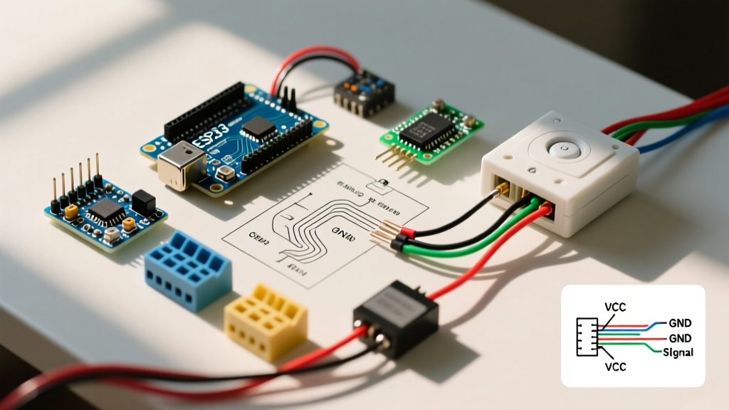
Standard 4-Wire Configuration (Line, Load, Neutral, Ground)
- Line (Hot): Typically black. Brings 120V AC from the breaker panel.
- Load: Typically red or blue. Carries the switched 120V AC to the appliance or fixture.
- Neutral: White. Completes the circuit to power the sensor's internal microprocessor and PIR array.
- Ground: Bare copper or green. Safety grounding for the sensor chassis.
Scenario 1: Standard Single-Pole Appliance Wiring (Leviton PR180-1LW)
For standard 120V appliances drawing under 5 Amps (approx. 600 Watts), such as a localized exhaust fan or workbench LED array, a standard wall-box PIR sensor like the Leviton PR180-1LW is ideal. Here is the precise wiring sequence.
- Power Verification: Turn off the breaker and verify zero voltage using a non-contact tester like the Klein Tools NCVT-4. Never rely solely on the wall switch position.
- Ground Connection: Connect the bare copper ground wire from the wall box to the green ground lead on the sensor. Torque to 14 in-lbs if using a terminal screw, or secure with a wire nut and pigtail.
- Neutral Connection: Bundle the sensor's white lead with the wall box's neutral (white) wires using a Wago 221 lever nut. Do not connect the sensor neutral to the ground wire; this will trip a GFCI/AFCI breaker immediately.
- Line Connection: Identify the constant hot wire from the panel (Line) and connect it to the sensor's black lead.
- Load Connection: Connect the sensor's red (or blue) lead to the wire feeding the appliance or fixture (Load).
Pro Tip: When using 12 AWG wire on a 20-Amp circuit, strip exactly 5/8-inch of insulation. Over-stripping exposes bare copper outside the terminal, creating a severe short-circuit hazard in cramped metal switch boxes.
Scenario 2: High-Load Appliance Control via Contactor (240V)
What happens when you need your motion sensor to trigger a 240V garage heater, a 3HP dust collector, or a heavy-duty ventilation system? Standard wall sensors are rated for a maximum of 10A to 15A at 120V. Attempting to run a 240V or high-amperage 120V appliance directly through a wall sensor will melt the internal TRIAC relay and cause a fire.
The solution is to use the motion sensor as a control signal to trigger a heavy-duty magnetic contactor, such as the Packard C240A (30A, 240V Contactor). This setup costs roughly $25 for the contactor and allows you to switch massive loads safely.
Wiring the Control Circuit (120V)
The motion sensor will only switch the 120V control circuit that powers the contactor's electromagnetic coil.
- Wire the motion sensor exactly as outlined in Scenario 1.
- Connect the Load wire from the motion sensor to the A1 terminal on the contactor coil.
- Run a separate 120V Neutral wire from your panel's neutral bar directly to the A2 terminal on the contactor coil.
Wiring the Appliance Load Circuit (240V)
The contactor handles the heavy lifting for the appliance.
- Run your 240V supply lines (typically Black and Red, or Black and White re-identified) from a dedicated double-pole breaker to the L1 and L2 terminals on the top of the contactor.
- Run the appliance's 240V feed wires from the T1 and T2 terminals on the bottom of the contactor directly to the appliance.
- Ensure the appliance ground is tied directly to the main panel ground bar, bypassing the contactor entirely.
Load Capacities and Wire Gauge Matrix
Selecting the correct wire gauge and sensor type is non-negotiable for code compliance and fire prevention. Refer to the matrix below for standard residential applications.
| Application Type | Sensor / Relay Model | Max Load | Required Wire Gauge | Breaker Size |
|---|---|---|---|---|
| LED Lighting / Small Fans | Lutron Maestro MS-OPS5MH | 5A (600W) | 14 AWG (or 12 AWG) | 15A / 20A |
| Standard 120V Appliances | Leviton PR180-1LW | 10A (1200W) | 12 AWG | 20A |
| 240V Heaters / Heavy Motors | Sensor + Packard C240A | 30A (7200W) | 10 AWG (Load) / 14 AWG (Control) | 30A (Load) / 15A (Control) |
Common Failure Modes and Troubleshooting
Even with a perfect wiring diagram for motion sensor setups, environmental and electrical variables can cause operational headaches. Here is how to diagnose the three most common issues encountered in the field.
1. LED Ghosting and Flickering
The Problem: The connected LED appliance or light fixture remains dimly lit (ghosting) or strobes rapidly when the sensor is in the 'OFF' state.
The Cause: The sensor's internal circuitry is leaking a tiny amount of standby current through the load wire to power its own microchip, which is enough to partially charge the capacitors in modern LED drivers.
The Fix: Install a Minimum Load Compensator (like the Lutron LUTMLC) in parallel across the load. This provides a dedicated bypass path for the leakage current. According to the U.S. Department of Energy's guidelines on occupancy sensors, ensuring proper load compatibility is essential for maximizing the lifespan of solid-state lighting and appliance drivers.
2. False Triggering (Ghost Switching)
The Problem: The sensor turns the appliance on when no one is in the room.
The Cause: PIR sensors detect changes in infrared heat signatures. If your sensor is mounted near an HVAC supply vent, a space heater, or a window with direct sunlight, the sudden shift in ambient air temperature will mimic human movement.
The Fix: Physically adjust the sensor's blinders to block the HVAC vent. If the environment is highly volatile (e.g., a dusty workshop with fluctuating temperatures), replace the PIR sensor with a Dual-Technology sensor (PIR + Ultrasonic) which requires both heat and physical motion to trigger.
3. Sensor Fails to Stay On (Timeouts)
The Problem: The appliance turns off while you are actively working in the room.
The Cause: The sensor's sensitivity is set too low, or the 'major motion' vs 'minor motion' threshold is miscalibrated. PIR sensors struggle to detect micro-movements (like typing at a desk or soldering on a workbench).
The Fix: Access the sensor's programming menu (usually via a sequence of button presses on the faceplate) and increase the sensitivity to 'High'. Alternatively, reduce the timeout delay from 5 minutes to 15 minutes to account for periods of stillness.
Safety and Code Compliance
When executing any appliance wiring tutorial, adherence to the National Electrical Code is mandatory. Specifically, NEC Article 404.2(C) dictates that a neutral conductor must be present at the switch location for electronic control devices. If you are retrofitting an older home built before the 1990s, you may find switch boxes lacking a neutral bundle. In these cases, you cannot legally or safely install a modern 4-wire motion sensor without pulling a new neutral wire from the nearest junction box or ceiling fixture. Bypassing the neutral requirement by using ground-as-neutral hacks is a severe shock hazard and will fail any municipal electrical inspection.
Conclusion
Mastering the wiring diagram for motion sensor applications transforms a standard room into an intelligent, energy-efficient space. Whether you are wiring a simple 120V Leviton switch for a closet exhaust fan or deploying a Packard contactor to control a 240V workshop heater, the principles of isolating the control circuit from the load circuit remain the same. Always verify your wire gauges, torque your terminal screws to manufacturer specifications, and respect the neutral wire requirements of modern electronic sensors.