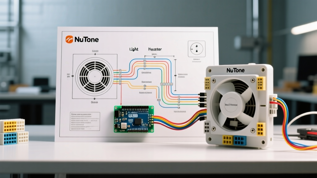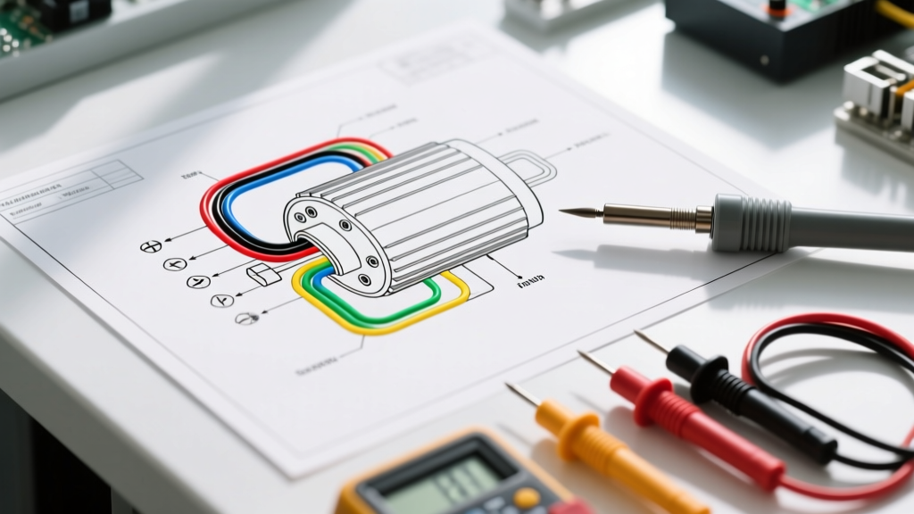

Decoding the Washing Machine Electric Motor Wiring Diagram
When a washing machine fails to agitate, spin, or drain, the drive motor is often the prime suspect. However, before you order a $140-$220 replacement part—such as the Whirlpool W10848314 direct drive motor or the GE WH49X20925 universal motor—you must verify the electrical pathway. Understanding a washing machine electric motor wiring diagram is the critical difference between a successful DIY repair and a tripped 20-amp breaker. This appliance wiring tutorial will walk you through the exact wire color codes, multimeter testing procedures, and mechanical edge cases you need to diagnose motor failures accurately.
⚠️ Critical Safety Warning: Capacitor Discharge & LOTO
Before touching any wiring harness, unplug the machine. According to OSHA's Lockout/Tagout standards, simply turning the dial to 'Off' is insufficient for appliance repair. Furthermore, traditional washer motors utilize a start capacitor (typically 50µF to 100µF at 125VAC-250VAC) that can retain a lethal charge for days. Always discharge the capacitor using a 20k-ohm, 5-watt wirewound resistor attached to insulated jumper leads before handling the motor terminals.
Anatomy of a Traditional Washer Motor Circuit
Most legacy and mid-efficiency top-load washing machines utilize a split-phase induction motor or a capacitor-start universal motor. These motors rely on two distinct internal coils: the run winding and the start winding. The wiring diagram routes 120V AC power through a timer or electronic control board, into a thermal overload protector, and then splits the current to achieve different speeds (e.g., slow agitate vs. fast spin).
A mechanical centrifugal switch is mounted on the motor shaft. When the motor reaches roughly 75% of its rated RPM, centrifugal weights push outward, opening the contacts to the start winding and engaging the run winding. If you are reading a washing machine electric motor wiring diagram and the motor hums but won't turn, this switch is usually the culprit.
Standard Wire Color Codes and Terminal Mapping
While manufacturers like Whirlpool, GE, and Maytag have slight variations, the industry relies on a relatively standardized color code for 120V AC washer motors. Below is the reference matrix you will use to trace your wiring harness.
| Wire Color | Terminal / Function | Circuit Role | Typical Resistance (Ohms) |
|---|---|---|---|
| Blue | Terminal 1 / Line 1 | High-Speed Run Winding (Spin Cycle) | 2.0Ω - 4.5Ω |
| Yellow | Terminal 2 / Line 2 | Common / Main Power Feed | N/A (Common junction) |
| Red | Terminal 3 / Start | Start Winding (Engages via Centrifugal Switch) | 10.0Ω - 15.0Ω |
| White | Terminal 4 / Neutral | Low-Speed Run Winding (Agitate Cycle) | 3.5Ω - 6.0Ω |
| Black | Terminal 5 / Thermal | Thermal Overload Protector (Auto-Reset) | 0.1Ω - 0.5Ω (Closed) |
| Orange | Terminal 6 / Capacitor | Start Capacitor Return Line | 10.0Ω - 15.0Ω (Shared with Red) |
Step-by-Step Multimeter Testing Procedure
To validate the wiring diagram against the physical motor, you need a digital multimeter (DMM) like the Fluke 117. Set your DMM to the lowest Ohms (Ω) setting and zero it out. Disconnect the main wire harness plug from the motor to isolate the stator windings.
- Test the Thermal Protector: Place your probes on the Black wire terminal and the Yellow (Common) terminal. You should read near zero ohms (0.1Ω - 0.5Ω). If you read 'OL' (Open Line), the internal thermal overload has tripped or burned out. Allow the motor to cool for 45 minutes and retest; if it remains open, the motor must be replaced.
- Test the High-Speed Run Winding: Measure between Blue and Yellow. A healthy reading is between 2.0Ω and 4.5Ω. A reading of 'OL' indicates a broken internal copper wire.
- Test the Low-Speed Run Winding: Measure between White and Yellow. Expect a slightly higher resistance than the high-speed winding, typically 3.5Ω to 6.0Ω.
- Test the Start Winding: Measure between Red and Orange. This should read between 10.0Ω and 15.0Ω. If this circuit is open, the motor will hum loudly, draw locked-rotor amperage (LRA) of up to 15 amps, and trip your breaker within seconds.
- Check for Ground Faults: Set your DMM to the highest Megohm range. Place one probe on the bare metal motor casing and the other on each terminal sequentially. Any reading other than 'OL' indicates the winding insulation has failed and is shorting to the chassis. Ensure your appliance grounding complies with the National Electrical Code (NEC) to prevent shock hazards.
Common Failure Modes and Edge Cases
Even if your multimeter tests show perfect continuity, mechanical and environmental edge cases can mimic wiring failures.
- Pitted Centrifugal Switch Contacts: Over thousands of cycles, the electrical arcing across the centrifugal switch contacts creates carbon buildup. The wiring diagram shows this switch in series with the start winding. If pitted, the switch may fail to disconnect the start winding once the motor reaches speed, causing the motor to overheat and the thermal protector to trip repeatedly.
- Agitate-to-Spin Transition Delay: Modern electronic control boards introduce a 2-to-4 second 'coast' period between agitate and spin. If you attempt to force the motor into spin while it is still rotating backward from agitation, the immense counter-electromotive force (CEMF) can shear the plastic drive coupler (e.g., Whirlpool part 285753A) rather than causing an electrical fault.
- Moisture Ingress in the Terminal Block: In laundry rooms with high ambient humidity, the 6-pin plastic Molex connector can suffer from copper oxidation. This adds 5-10 ohms of parasitic resistance, causing a voltage drop that prevents the motor from reaching the RPM threshold required to throw the centrifugal switch.
Expert Insight: 'Never bypass the thermal overload protector by jumping the black wire directly to the power feed. The U.S. Department of Energy and UL safety standards mandate this component to prevent stator fires during mechanical lock-ups, such as a seized transmission or jammed water pump.'
The 2026 Landscape: BLDC and Inverter Motors
As of 2026, over 75% of new front-load and high-efficiency top-load washing machines have abandoned traditional split-phase AC motors in favor of Brushless DC (BLDC) inverter motors. If you are looking at a washing machine electric motor wiring diagram for a modern LG, Samsung, or Whirlpool front-loader, you will not see standard AC wire colors.
Instead, you will find a 5-pin or 7-pin harness. Three thick wires (usually U, V, W phases colored Yellow, Blue, and Red) carry high-voltage 3-phase AC generated by the machine's internal inverter board. The remaining 4-5 thin wires connect to internal Hall-effect sensors that report rotor position back to the main control board. Do not apply 120V AC directly to these terminals. Diagnosing a BLDC motor requires checking the Hall sensor outputs (typically 5V DC square waves) using an oscilloscope or a specialized appliance diagnostic tool, rather than simple resistance testing.
Frequently Asked Questions (FAQ)
Why does my washer motor hum but not start, even though the wiring tests good?
If the windings test within spec but the motor only hums, the start capacitor is likely dead, or the centrifugal switch is mechanically stuck in the open position. Remove the motor and manually push the centrifugal switch actuator upward while testing the start winding terminals for continuity.
Can I reverse the direction of a washing machine motor?
Yes, traditional washer motors reverse direction to switch between agitate and spin. This is achieved by the timer or control board swapping the polarity of the start winding relative to the run winding. You cannot permanently reverse it by simply flipping the main power plug; the control board must manage the sequence.
What wire gauge should I use if I need to replace a damaged motor pigtail?
Always use 14 AWG stranded copper wire with 600V THHN/THWN insulation for the main power feed (Line and Neutral). For the low-current thermal protector or sensor lines, 16 AWG stranded is acceptable. Ensure all splices are made using heat-shrink butt connectors with integrated solder, never standard vinyl electrical tape.