
The Anatomy of a 48V Scooter Electrical System
Building or upgrading a custom electric scooter in 2026 requires a precise understanding of high-current power delivery and low-voltage signal logic. While 36V systems remain common in entry-level commuter models, the 48V architecture (specifically 13S and 14S lithium-ion configurations) has become the undisputed standard for performance builds, offering the torque and top speed required for off-road and heavy-duty urban commuting. This comprehensive 48v electric scooter wiring diagram walkthrough will guide you through integrating a battery management system (BMS), a Field Oriented Control (FOC) sine wave controller, and peripheral inputs without triggering overcurrent faults or frying your Hall sensors.
Component & Wire Gauge Matrix
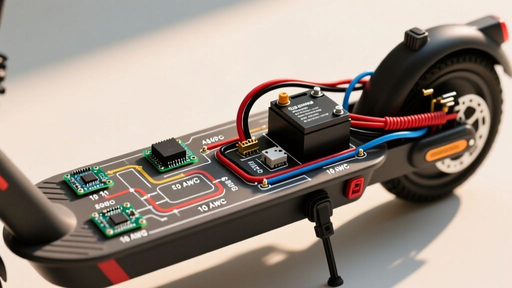
Using the correct American Wire Gauge (AWG) is critical. Undersized wires on a 48V system pulling 25A+ continuous will suffer from severe voltage sag, thermal melting, and potential fire hazards. Below is the exact specification matrix for a standard 48V 1000W-1500W build.
| Component Circuit | Nominal Voltage | Recommended Wire Gauge | Connector Standard |
|---|---|---|---|
| Main Battery to Controller | 48V - 58.8V | 10 AWG Silicone | XT90 (Anti-Spark) |
| Motor Phase Wires | Variable AC | 12 AWG Silicone | 4.2mm Bullet Connectors |
| Motor Hall Sensors | 5V DC | 22 AWG PVC | JST-SM 2.54mm (5-Pin) |
| Throttle & Display | 5V DC | 24 AWG PVC | JST-SM 2.54mm (3-Pin) |
| Brake Cut-off Levers | 5V - 58.8V | 22 AWG PVC | JST-SM 2.0mm (2-Pin) |
Step 1: High-Current Battery & BMS Integration
The foundation of your 48v electric scooter wiring diagram is the battery pack. A nominal 48V pack is typically configured in a 13S (48.1V nominal, 54.6V fully charged) or 14S (51.8V nominal, 58.8V fully charged) layout. According to Battery University's guidelines on series configurations, ensuring balanced cell groups is vital before connecting the main discharge leads.
For the main discharge loop, solder 10 AWG silicone wires directly to the BMS P- (Discharge Negative) and the battery's main positive terminal. Do not rely on mechanical screw terminals for high-amperage scooter builds; vibration will loosen them and cause arcing. Solder an XT90 connector to the controller side. The XT90 features a built-in spark-suppression resistor pin that pre-charges the controller's capacitors before the main positive pin makes contact, preventing the destructive voltage spikes that degrade MOSFETs over time.
Step 2: The Ignition Switch Loop (The Most Common Pitfall)
The most frequent error in DIY scooter wiring is misunderstanding the controller's power-on logic. If you simply connect the thick red and black battery wires to the controller, it will not turn on. Modern FOC controllers require a 'Lock' or 'Ignition' signal.
- Locate the Ignition Wire: Find the thin red wire (usually 18 AWG) coming out of the controller's main harness, often labeled 'LOCK', 'IGN', or 'DC+'. This wire must receive full battery voltage to wake the controller's internal logic board.
- Wire the Key Switch: Splice a heavy-duty keyed ignition switch or a momentary push-button between the battery's main positive terminal (before the XT90) and the controller's thin red ignition wire.
- Add a BMS Sleep Relay (Optional but Recommended): To prevent parasitic drain when the scooter is parked, wire the BMS wake-up signal through the same ignition switch so the BMS completely disconnects when the key is off.
Step 3: Motor Phase & Hall Sensor Wiring
Connecting the hub motor requires matching both the high-current phase wires and the low-voltage Hall effect sensors. The phase wires (Yellow, Green, Blue) carry the pulsed DC that drives the motor. Use 12 AWG wire and 4.2mm gold-plated bullet connectors, sealing the joints with adhesive-lined heat shrink to prevent moisture ingress.
Hall Sensor Phase Angle Calibration
The 5-pin JST-SM Hall sensor connector carries 5V power (Red), Ground (Black), and three signal wires (Yellow, Green, Blue). Most 48V scooter hub motors operate on a 120-degree Hall sensor phase angle. If your controller is set to 60 degrees (or if the wire colors do not match the manufacturer's pinout), the motor will stutter, draw massive current, and refuse to spin. Always perform a 'Hall/Phase Combination Test' using your controller's diagnostic software or learning wire before applying full throttle.
Step 4: Low-Voltage Peripherals (Throttle & Brakes)
Peripherals operate on the 5V voltage regulator internal to the controller. Wiring these incorrectly can send 48V directly into the 5V logic rail, instantly destroying the microcontroller.
- Throttle (3-Pin): Red (5V), Black (Ground), White/Green (Signal). The signal wire outputs a linear voltage from 0.8V (idle) to 4.2V (full throttle). Always verify these voltages with a multimeter before plugging it into the controller.
- Brake Cut-offs (2-Pin): Most modern controllers use 'Active Low' brake levers. This means the brake circuit is normally held at 5V, and pulling the lever shorts the signal wire to ground, triggering the motor cut-off. Ensure your levers match the controller's logic (Active Low vs. Active High).
- Regenerative Braking (E-ABS): If utilizing a single-wire E-ABS connection, ensure it is routed to a dedicated E-ABS pin on the controller, not a standard digital brake pin, as the voltage return during regen can exceed 5V.
Troubleshooting Edge Cases & Failure Modes
Even with a perfect 48v electric scooter wiring diagram, real-world variables can cause faults. Here is how to diagnose the most common edge cases:
Motor Stutters and Stops Under Load
Cause: BMS Overcurrent Protection or Voltage Sag.
Fix: If your controller is set to draw 30A peak, but your BMS is rated for 25A continuous, the BMS will cut power during hard acceleration. Upgrade to a 40A Smart BMS or reduce the controller's phase current limit in the software settings.
Scooter Powers On, But Throttle Does Nothing
Cause: Brake lever stuck engaged or Hall sensor failure.
Fix: Disconnect both brake levers. If the throttle works, a misaligned brake magnet is keeping the cut-off circuit permanently grounded. If it still fails, unplug the motor Halls and use a multimeter to check for 5V on the red wire and a fluctuating 0-5V on the signal wires as you spin the wheel by hand.
Controller Overheating at Low Speeds
Cause: Phase/Hall mismatch.
Fix: The controller is firing the MOSFETs out of sequence with the rotor position, creating massive reactive heat instead of mechanical rotation. Run the auto-learning wire sequence to map the correct phase angle.
Safety Warning: Lithium-ion battery fires in micromobility devices have become a severe hazard. The National Fire Protection Association (NFPA) strongly advises against using uncertified battery packs and chargers. Always ensure your 48V battery pack is assembled with a UL-recognized BMS and housed in a fire-retardant enclosure. Furthermore, follow the CPSC micromobility safety guidelines regarding proper charging environments and post-crash electrical inspections.
Final Bench Test Protocol
Before zip-tying wires and mounting the deck, elevate the rear wheel off the ground. Turn the ignition key, verify the display boots up, and gently roll the throttle to 10%. Listen for abnormal grinding (indicating a phase mismatch) and monitor the controller temperature. Once verified, secure all high-current wires with stainless steel P-clips and wrap low-voltage harnesses in braided nylon sleeving to protect against abrasion and road debris.