
Decoding the Complexity of Forest River RV Electrical Schematics
Owning a Forest River RV—whether it is a rugged Cherokee toy hauler, a spacious Wildwood travel trailer, or a motorized Georgetown—means managing a rolling microgrid. Unlike residential wiring, which relies on a single 120V/240V AC grid, an RV electrical system is a hybrid beast. It seamlessly blends 120V AC shore power, 12V DC coach batteries, and increasingly, factory-installed 48V DC lithium architectures found in newer 2025 and 2026 models. When a circuit fails or you plan a solar upgrade, guessing is not an option. You need to understand electrical Forest River RV wiring diagrams. This guide breaks down how to read these schematics, trace specific circuits, and troubleshoot the most common failure points in Forest River's power distribution networks.
The Anatomy of Forest River RV Electrical Systems
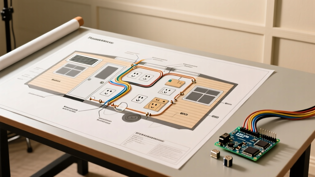
Before diving into the schematic symbols, you must understand the physical layout of a Forest River electrical system. The diagrams are generally split into three distinct sub-systems:
- Chassis 12V DC: Powers the engine, exterior running lights, and chassis battery (primarily in motorized models like the Forester or Georgetown).
- Coach 12V DC: Powers interior LED lighting, water pumps, slide-out motors, and control boards for appliances like the Dometic or Furrion refrigerators.
- Coach 120V AC: Powers the roof air conditioners, microwave, residential refrigerators, and AC receptacles via shore power or an onboard generator.
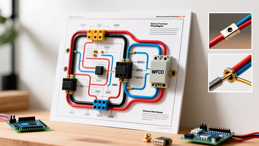
The central hub for the coach systems is the Power Distribution Center (PDC), most commonly manufactured by WFCO Technologies or Progressive Dynamics. In your wiring diagram, the PDC is represented as a large centralized node where AC breakers and DC fuses intersect.
Key Component Identifiers in Forest River Diagrams
Forest River schematics use specific nomenclature and symbols. Below is a translation matrix for the most common components you will encounter on the printed diagrams tucked inside your owner's packet.
| Schematic Label / Symbol | Real-World Component | Typical Forest River Application |
|---|---|---|
| CONV / PDC | WFCO WF-8955-PEC Power Center | Main AC/DC distribution and battery charging (55A) |
| ATS | Automatic Transfer Switch | Switches AC load between Shore Power and Generator |
| SLIDE CTRL | Lippert Smart Module / ONEcontrol | Multiplex node controlling 12V slide-out motors |
| GFI / GFCI | Ground Fault Circuit Interrupter | First outlet in the bathroom/kitchen daisy-chain |
| BIRD | Bidirectional Isolator Relay Delay | Combines chassis and coach batteries for charging |
Step-by-Step: Tracing a 120V AC Circuit in Your Diagram
Let us trace a 120V AC circuit for a roof air conditioner (e.g., a 15,000 BTU Furrion or Coleman Mach unit). Understanding this path is critical for diagnosing tripped breakers or voltage drops.
- Locate the Shore Input: Find the 30A (TT-30) or 50A (14-50R) inlet on the diagram. For a 50A Forest River Wildwood, you will see four wires: Black (Hot 1), Red (Hot 2), White (Neutral), and Green (Ground).
- Follow the ATS (If Equipped): If your RV has a generator, the diagram will show the shore input routing into an Automatic Transfer Switch. The ATS prioritizes generator power. If the ATS fails, neither source will reach the main panel.
- Enter the Main PDC Breaker: The AC lines enter the WFCO power center. A 50A rig will have a 50A dual-pole main breaker. The diagram will show Hot 1 and Hot 2 splitting to different branch breakers.
- Trace the Branch Circuit: Find the 20A breaker labeled 'A/C 1'. The diagram shows a single 12 AWG or 10 AWG Romex cable (Black, White, Bare) running from the breaker to the ceiling junction box.
- Identify the Thermostat Loop: Note that the 120V diagram often intersects with a 12V DC control loop. The thermostat uses 12V DC to send a signal to the A/C control board, which then engages the 120V compressor contactor.
Expert Troubleshooting Tip: Forest River uses standard solid-copper Romex for 120V AC wiring. Due to constant road vibration, the set-screws on the WFCO main breakers and GFCI receptacles can loosen over time. If your diagram shows a complete circuit but you have no power, physically tighten all AC terminal screws at the PDC and the first GFCI outlet in the daisy chain before replacing any components.
Troubleshooting 12V DC Coach Wiring Using Schematics
The 12V DC side is where most RVers experience issues. Forest River typically uses 14 AWG wire for lighting and 12 AWG or 10 AWG for high-draw items like slide-outs and stabilizer jacks. In the diagrams, DC ground is almost universally represented by a white wire, while +12V is black or red. This is opposite to standard automotive wiring (where black is ground), which frequently confuses DIYers.
The Reverse Polarity Fuse Trap
If your entire 12V coach is dead but your battery reads 12.6V at the terminals, look at your wiring diagram for the Reverse Polarity Fuses. On WFCO WF-8900 series panels, Forest River installs two 30A or 40A automotive blade fuses directly on the DC distribution board, usually hidden behind a small plastic snap-cover. These protect the converter and wiring if the battery is hooked up backward. If one blows, half your DC panel dies. If both blow, the entire coach loses 12V power, and the converter cannot charge the battery.
Matrix: Common Forest River 12V DC Failure Modes
Use this diagnostic matrix alongside your specific floorplan wiring diagram to isolate 12V faults quickly.
| Symptom | Diagram Check Point | Physical Test & Resolution |
|---|---|---|
| Slide-out moves 2 inches then stops | Check voltage drop across Slide Motor relay and 30A inline breaker. | Load-test the battery. High resistance in the 10 AWG feed wire or a failing Lippert motor drawing >25A under load. |
| Water pump cycles on/off without faucets open | Trace 12V feed to pump switch and check for parallel check-valve paths. | Inspect the accumulator tank pressure. Check for micro-leaks in PEX fittings that drop pressure, triggering the diagram's pressure switch. |
| Interior LEDs flicker when A/C kicks on | Review WFCO Converter DC output rating vs. total DC load. | The WFCO converter may be failing to filter AC ripple. Test DC output with an oscilloscope; replace with a Progressive Dynamics PD4655 if ripple exceeds 1.5V. |
Multiplex Wiring: The Lippert ONEcontrol Shift
If you are reading diagrams for a 2024, 2025, or 2026 Forest River model equipped with the Lippert ONEcontrol or Global Link multiplex system, traditional point-to-point wiring diagrams no longer apply. Instead of a dedicated physical wire running from a wall switch to a light fixture, the wall switch sends a digital signal over a CAN bus or LIN bus network to a centralized Lippert Smart Module. The Smart Module then switches the high-current 12V power to the light.
When troubleshooting multiplex diagrams, you must look for network termination resistors (usually 120 ohms) and check for CAN-High and CAN-Low voltage states (typically 2.5V and 2.5V at idle, shifting to 3.5V and 1.5V during data transmission). A break in the thin communication harness will disable multiple seemingly unrelated circuits.
Solar and Lithium Upgrades: Modifying the Factory Diagram
Many owners upgrade their Forest River RVs with aftermarket solar and LiFePO4 lithium batteries. When doing this, you must physically and schematically alter the factory wiring diagram. The stock WFCO WF-8955 lead-acid converter outputs a fixed 13.6V, which will never fully charge a lithium battery to its required 14.4V absorption voltage.
Required Schematic Modifications:
- Converter Swap: Replace the stock WFCO deck with a WFCO WF-9855-L (Lithium specific) or a Victron MultiPlus inverter/charger. Update your diagram to reflect the new 14.4V DC bus parameters.
- Wire Gauge Upgrades: Lithium batteries can accept charge currents exceeding 100A. The factory 6 AWG battery cables must be upgraded to 2/0 AWG welding wire to prevent voltage drop and melting, a critical update that must be noted on your revised as-built schematic.
- BMS Integration: Route a communication cable from the lithium Battery Management System (BMS) to your new solar charge controller (e.g., Victron SmartSolar MPPT) to allow the BMS to halt charging if cell voltages exceed safe limits.
Where to Source Official Forest River Schematics
Finding the exact diagram for your rig can be frustrating, as Forest River builds by floorplan and production run rather than strict model years. To get the correct electrical Forest River RV wiring diagrams, follow these protocols:
- The VIN is Mandatory: Call Forest River customer service or your original dealer with your 17-digit VIN. The build sheet tied to your VIN dictates exactly which WFCO panel, Lippert harness, and Furrion appliance package was installed on the line.
- Check the Physical PDC Packet: Open the door to your WFCO or Progressive Dynamics power center. Manufacturers almost always zip-tie a folded, physical schematic packet to the inside of the breaker panel door or the adjacent stud.
- Leverage the Community: The Forest River Forums maintain massive repositories of user-scanned PDF schematics organized by brand (Cherokee, Salem, Rockwood) and floorplan. Search your specific floorplan number (e.g., 26DBUD) rather than just the model year.
Safety Standards and Final Thoughts
Always remember that RV electrical systems are governed by the Recreation Vehicle Industry Association (RVIA) standards and the National Electrical Code (NEC) Article 551. When modifying or repairing circuits based on your diagrams, ensure all 120V AC connections are made inside approved junction boxes, and all 12V DC connections are crimped with heat-shrink terminals—never use wire nuts in high-vibration DC environments. For detailed component specifications and replacement manuals, consult WFCO Technologies directly. By mastering your RV's wiring diagrams, you transition from a passive owner to an empowered technician, capable of keeping your rig powered safely through any adventure.