
Understanding the Boiler Electrical Wiring Diagram
Wiring a hydronic heating boiler requires a precise understanding of control logic, line voltage distribution, and low-voltage thermostat integration. Whether you are retrofitting a legacy cast-iron unit or installing a modern condensing boiler, the boiler electrical wiring diagram serves as the master blueprint. In 2026, with the widespread adoption of smart thermostats and ECM (Electronically Commutated Motor) circulators, interpreting these schematics correctly is more critical than ever to prevent control board burnout and ensure compliance with the latest NEC (National Electrical Code) standards.
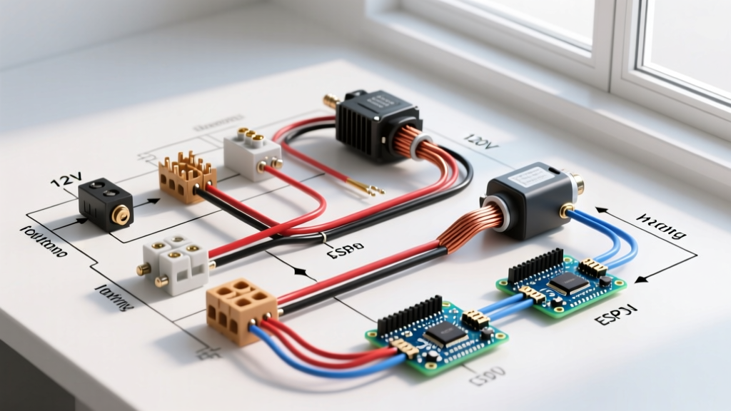
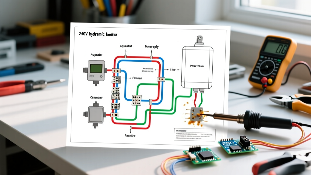
This guide dissects the standard 240V/120V residential boiler wiring architecture, focusing on the interplay between the main disconnect, the aquastat (temperature limit control), the circulator relay, and the gas valve or ignition module.
Core Components in the Wiring Schematic
Before making any terminations, identify these primary nodes on your specific manufacturer's schematic:
- Main Disconnect & Fusing: Typically a 30A or 40A double-pole breaker feeding a local fused disconnect (e.g., Square D H221N or Eaton DH221NRK).
- Control Transformer: Steps down 120V/240V line voltage to 24VAC for the thermostat (T-T) and gas valve circuit. Usually rated at 40VA to 75VA for modern smart thermostats requiring a C-wire.
- Aquastat / Primary Control: Devices like the Honeywell L8148E or Taco PC700-2P manage the high-limit cutoff and switch the circulator relay based on heat calls.
- Circulator Pump Relay: Isolates the 120V pump motor from the low-voltage thermostat signal.
- Draft Inducer / Exhaust Fan: Found on high-efficiency (90%+ AFUE) models, requiring 120V power and proving-switch feedback loops.
Step-by-Step Wiring Procedure for a Standard Gas Boiler
Phase 1: Line Voltage Feed (240V to 120V)
Most residential boilers operate internal controls on 120V, even if fed by a 240V branch circuit.
- Run 10/2 NM-B (Romex) or THHN in conduit from a dedicated120V/20A dedicated breaker (or 240V/30A if required by the unit's internal transformer) to a local service disconnect within sight of the boiler.
- From the disconnect, route 12/2 MC (Metal Clad) cable into the boiler's primary junction box.
- Terminate Line (L1/Black), Neutral (White), and Ground (Bare/Green). Crucial: NEC Article 250 requires the equipment grounding conductor to be bonded to the boiler chassis. Do not rely on the gas pipe for grounding.
Phase 2: The 24V Control Circuit (T-T and Gas Valve)
The 'T-T' (Thermostat) terminals on the aquastat or integrated control board complete the 24V circuit.
- Connect the 18/2 thermostat wire from the wall thermostat to the T-T terminals. Polarity generally does not matter on legacy R-W setups, but for 2026 smart thermostats (like the Ecobee SmartTherm Premium), you must connect the 'C' (Common) wire directly to the 24VAC transformer's common terminal to prevent power stealing, which can cause the gas valve to chatter.
- Wire the 24V gas valve. Ensure the ground wire from the valve is tied to the chassis ground. A floating ground on the ignition module will cause the flame sensor to fail to detect the microamp flame signal, resulting in short-cycling.
Phase 3: Circulator and Limit Controls
- Wire the 120V circulator pump (e.g., Taco 007e or Grundfos UPS15-58FC) to the 'C1' and 'C2' (or 'L1' and 'N') terminals on the circulator relay.
- Install the high-limit aquastat probe into the boiler's immersion well. Wire the 120V line through the aquastat's 'B1-B2' (Break) terminals so that if the boiler exceeds 180°F–200°F, it physically cuts power to the gas valve and inducer, while allowing the circulator (wired to 'W-W' or 'Make' terminals) to continue running to dissipate residual heat.
Wire Gauge and Component Sizing Matrix
Using the correct wire gauge prevents voltage drop, which is the leading cause of premature contactor and relay failure in heating systems.
| Circuit / Component | Voltage | Wire Gauge (Copper) | Max Overcurrent Protection | 2026 Code / Best Practice Note |
|---|---|---|---|---|
| Main Power Feed (Standard) | 120V | 12 AWG THHN / NM-B | 20 Amp | Must be dedicated; no shared neutrals. |
| Main Power Feed (High-Capacity) | 240V | 10 AWG THHN / NM-B | 30 Amp | Required for boilers with large internal step-down transformers. |
| Thermostat (24V Low Voltage) | 24VAC | 18 AWG (up to 50ft) / 16 AWG (50ft+) | N/A (Class 2) | Use shielded cable if running parallel to 120V lines to prevent EMI. |
| Circulator Pump (Standard) | 120V | 14 AWG (if under 15A) | 15 Amp | Use high-temp (90°C) wire near the pump flange. |
| Boiler Loop (Grounding) | N/A | 10 AWG Bare / Green | N/A | Bond to cold water pipe and grounding electrode system. |
2026 Troubleshooting: ECM Pumps and Smart Thermostats
The shift toward ECM (Electronically Commutated Motor) circulators like the Grundfos ALPHA or Taco 00-VarioFit has changed how we read boiler electrical wiring diagrams. Unlike standard PSC (Permanent Split Capacitor) motors that draw high locked-rotor amps on startup, ECM pumps require clean, stable sine waves.
Failure Mode: If you wire an ECM pump through a standard mechanical relay with pitted contacts, the resulting voltage harmonic distortion can cause the pump's internal inverter to throw an 'E-04' or communication fault. Solution: Use solid-state relays (SSRs) or high-grade contactors rated for motor loads (FLA/FLA ratings) when switching modern ECM pumps.
Furthermore, the 2026 NEC and local mechanical codes increasingly mandate NFPA 70 (NEC) compliant GFCI/AFCI protection for 120V boiler receptacles in basements. However, the high inrush current of older draft inducer motors can cause nuisance tripping on standard 2026 AFCI breakers. Always verify the boiler manufacturer's compatibility list for AFCI breakers before finalizing the panel termination.
Safety and Code Compliance Checklist
Before energizing the system, verify the following against your local AHJ (Authority Having Jurisdiction) requirements:
- Emergency Switch: Is a red-plated emergency disconnect installed at the top of the basement stairs or outside the boiler room door? (Required by NFPA 31 / ICC Mechanical Code).
- Transformer Sizing: Calculate total VA. A modern Wi-Fi thermostat (15VA) + Gas Valve (15VA) + Zone Relays (10VA each) easily exceeds a standard 40VA transformer. Upgrade to a 75VA or 100VA transformer to prevent low-voltage dropout during ignition.
- Ground Continuity: Use a multimeter to verify less than 1 ohm of resistance between the boiler chassis and the main panel ground bus.
Frequently Asked Questions
Why does my boiler wiring diagram show a 'C' wire but my old thermostat didn't use one?
Legacy thermostats were purely mechanical switches or battery-operated. Modern smart thermostats require continuous 24VAC power for Wi-Fi and displays. If your boiler's wiring diagram doesn't explicitly label a 'C' terminal, it is located at the secondary (24V) side of the control transformer. Connect the 'C' wire there, ensuring you do not blow the 3A automotive-style fuse usually located on the control board.
Can I wire two circulator pumps to a single relay?
Yes, provided the combined Full Load Amps (FLA) of both pumps do not exceed the relay's contact rating (typically 15A or 1/2 HP for standard Honeywell RA89A relays). If the combined load is higher, you must use the primary relay to switch the coil of a secondary, higher-capacity definite-purpose contactor.
What causes a 24V transformer to burn out repeatedly?
A repeatedly burning transformer is almost always caused by a short circuit in the field wiring (the thermostat wire) or a failing gas valve coil drawing excessive amperage. Before replacing the transformer, disconnect the field wires and measure resistance. It should read between 20 and 80 ohms. If it reads near 0 ohms, you have a short in the wall.