
The Myth of the Reflow Oven: Why Hand Soldering SMD is Viable
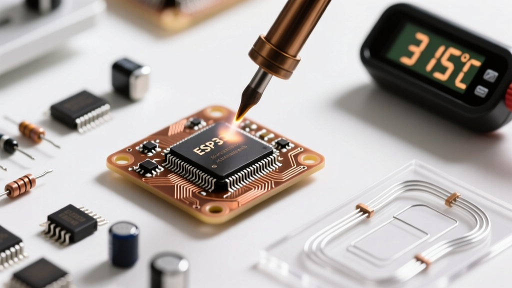
When transitioning from through-hole components to surface-mount devices (SMD), many beginners assume they need to invest hundreds of dollars in a hot air rework station, a stencil, and a reflow oven. While those tools are essential for high-volume manufacturing, soldering SMD parts by hand is not only entirely viable for prototyping and repairs, but it also builds a profound understanding of solder metallurgy and thermal management. With the right micro-tip geometry, precise temperature control, and an understanding of capillary action, you can reliably hand-solder components down to 0603 imperial (1.6mm x 0.8mm) and SOIC-16 integrated circuits right on your workbench.
Your 2026 SMD Toolkit: Exact Specs & Costs
To succeed at micro-soldering, your tools must bridge the gap between macro-scale heat application and micro-scale component pads. Here is the exact, field-tested toolkit you need, complete with current market pricing.
1. The Soldering Iron & Tip Geometry
Forget the standard chisel tips that came with your entry-level iron. You need an iron with rapid thermal recovery and interchangeable micro-tips.
- Budget Option: Pinecil V2 (~$26). Powered by a RISC-V chip, it supports PD 65W adapters and recovers heat exceptionally well for its price class.
- Prosumer Option: Hakko FX-888D (~$110) or Pine64 Pinecil V2 with a genuine Hakko T18-B2 (conical, 0.5mm radius) or T18-D12 (1.2mm micro-chisel). The micro-chisel is vastly superior to conical tips because it provides a larger surface area for thermal transfer while maintaining a fine edge for precision work.
2. Solder Alloy & Wire Diameter
Diameter is critical. Standard 0.8mm through-hole solder will instantly flood SMD pads, causing bridges. You must use ultra-fine wire.
- Alloy: Sn63/Pb37 (Eutectic) is highly recommended for beginners. It melts at exactly 183°C and transitions instantly from liquid to solid, preventing cold joints caused by micro-movements during the cooling phase.
- Diameter: 0.015 inches (0.38mm). Brands like Kester (Series 44) or MG Chemicals offer this in 4oz spools for roughly $18 to $24.
3. Flux Chemistry
Flux is the actual hero of SMD soldering. It removes oxidation and reduces surface tension, allowing the solder to flow via capillary action.
- Tacky Flux (Syringe): Chip Quik SMD291AX or Amtech NC-559-V2-TF (~$16). This viscous, no-clean flux holds components in place before soldering and provides long-lasting activation at high temperatures.
4. Precision Tweezers & Wick
- Tweezers: Dumont #5 ESD-safe carbon steel tweezers (~$35). The ultra-fine tips are required to manipulate 0603 resistors without flicking them across the room.
- Desoldering Wick: Goot Wick CP-2060 (2.0mm width) or Chemtronics Soder-Wick. You will make bridges; wick is your eraser.
SMD Component Dimensions & Difficulty Matrix
Understanding the nomenclature of SMD parts is crucial. Passives (resistors, capacitors) are typically named using imperial dimensions, while ICs use package acronyms. Below is a matrix to help you gauge the difficulty of soldering SMD parts by hand.
| Package Type | Imperial / Metric | Dimensions (L x W) | Hand-Solder Difficulty | Recommended Tip |
|---|---|---|---|---|
| Passive (0402) | 0402 / 1005 | 1.0mm x 0.5mm | Extreme (Microscope required) | 0.4mm Conical |
| Passive (0603) | 0603 / 1608 | 1.6mm x 0.8mm | Moderate (Magnification recommended) | 1.2mm Micro-Chisel |
| Passive (0805) | 0805 / 2012 | 2.0mm x 1.25mm | Easy (Naked eye viable) | 1.6mm Chisel |
| SOIC-8 IC | 1.27mm Pitch | 5.0mm x 4.0mm | Moderate (Tack & Drag method) | 2.4mm Hoof / Knife |
| TQFP-32 IC | 0.80mm Pitch | 9.0mm x 9.0mm | Hard (Requires drag soldering) | Knife Tip / Mini-Wave |
Walkthrough 1: Soldering Passives (0603 & 0805)
The most reliable method for resistors and capacitors is the One-Pad Tack Technique. Attempting to heat both pads simultaneously with a single iron while holding tweezers is a recipe for component ejection and misalignment.
- Prep the Pad: Apply a microscopic dot of tacky flux to one of the PCB pads using a toothpick or syringe.
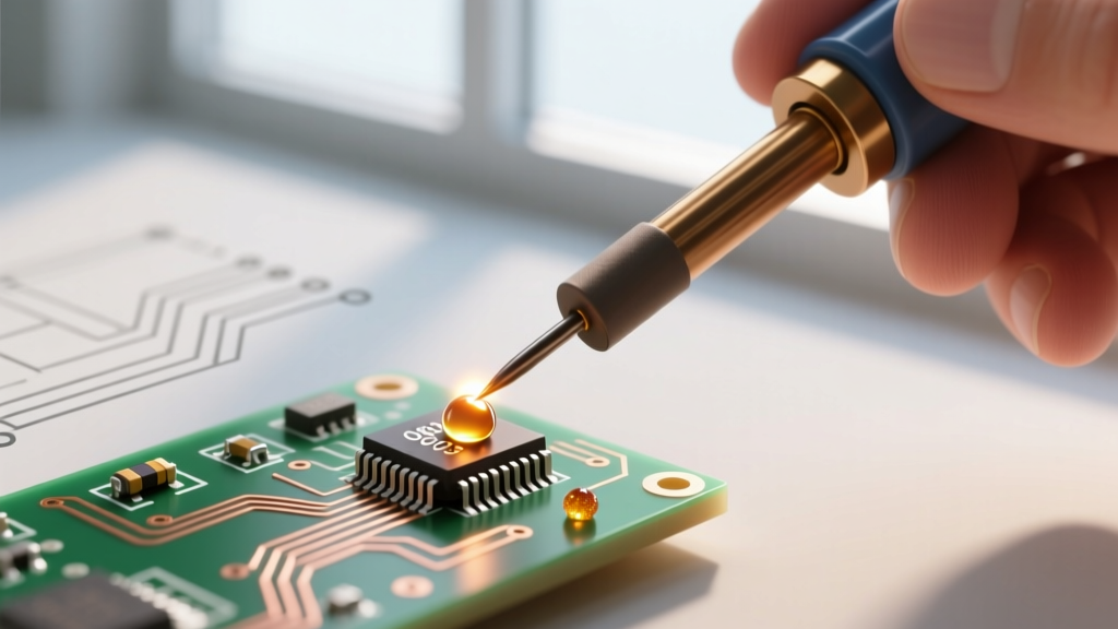
- Tin the Pad: Touch your iron to the fluxed pad and feed exactly 1mm of 0.015" solder wire. You should see a small, shiny dome. Remove the iron and let it solidify.
- Set the Component: Grab the 0603 resistor with your Dumont tweezers. Re-heat the tinned pad with your iron. While the solder is molten, slide the component into place so one of its end caps is submerged in the solder pool.
- Cool and Release: Remove the iron first, hold the component perfectly still for 2 seconds until the solder freezes, then release your tweezers.
- Solder the Second Pad: Apply a touch of liquid or tacky flux to the opposite pad. Touch the iron to the pad and the component cap simultaneously, feed a tiny amount of solder, and remove. The flux will pull the solder into a perfect, concave fillet.
Pro-Tip: If the component shifts or sits unevenly (known as 'tombstoning'), apply flux to both pads and re-heat the skewed side. The surface tension of the molten solder will automatically snap the component into perfect alignment.
Walkthrough 2: Integrated Circuits (SOIC & SOP Packages)
When soldering SMD parts with multiple pins (like an SOIC-8 microcontroller or a SOIC-16 logic gate), the One-Pad Tack method evolves into the Corner-Tack and Inspect workflow.
Step 1: Alignment and Corner Tacking
Apply a thin, even layer of tacky flux across all pads on the PCB footprint. Using your tweezers, carefully align the IC pins with the copper pads. Ensure pin 1 (indicated by a dot or notch on the IC) aligns with the silkscreen marker on the board. Once aligned, solder only the top-left and bottom-right corner pins. This locks the chip in place.
Step 2: Visual Verification
Before proceeding, use a magnifying lamp or digital microscope to inspect the alignment. If the chip is crooked, re-heat the corner pads, nudge the chip with tweezers, and let it cool. Never attempt to solder the remaining pins if the alignment is off.
Step 3: The Drag Soldering Method (For 0.8mm Pitch and Below)
For fine-pitch ICs, individual pin soldering is too slow and risks pad lift. Instead, use drag soldering:
- Apply a generous amount of liquid rosin flux (like Kester 186) over the entire row of pins.
- Load your micro-chisel or hoof tip with a moderate amount of solder.
- Drag the iron slowly across the pins at a 45-degree angle. The flux will break the surface tension, and capillary action will pull the exact right amount of solder onto each pin, leaving the gaps clean.
- If a bridge forms between two pins, do not panic. Clean your iron tip on a brass sponge, apply more flux to the bridge, and touch the iron to the bridge. The excess solder will wick up onto the iron or flow down onto the adjacent pads.
Troubleshooting Common SMD Failure Modes
Even experienced engineers encounter metallurgical anomalies. Here is how to diagnose and fix the most common issues when soldering SMD parts.
Tombstoning (The Drawbridge Effect)
The Problem: The passive component stands straight up on one end, resembling a tombstone.
The Cause: Uneven heating. One pad reached the solder's melting point before the other, and the surface tension of the molten solder pulled the component upright.
The Fix: Ensure your iron tip is clean and tinned. Heat the pad and the component cap simultaneously. If using a PCB with heavy ground planes, the ground plane will act as a heatsink, drawing heat away from the pad. In 2026, using a $40 silicone PCB pre-heater mat set to 100°C underneath the board eliminates this thermal disparity.
Solder Bridges (Shorts)
The Problem: Solder connects two adjacent IC pins, causing a dead short.
The Cause: Excessive solder volume, lack of flux, or a dirty iron tip.
The Fix: Do not try to suck it up with a vacuum pump. Apply a thick layer of Chip Quik tacky flux over the bridge. Take a high-quality copper desoldering wick (2.0mm), place it over the bridge, and press your iron on top of the wick. The wick will absorb the excess solder via capillary action in roughly 3 seconds. Clean the residue with 99% Isopropyl Alcohol (IPA) and a lint-free Kimwipe.
Cold Joints and Grainy Fillets
The Problem: The solder joint looks dull, gray, and crystalline rather than shiny and concave.
The Cause: The iron temperature was too low, the pad was oxidized, or the joint was moved before the eutectic alloy fully solidified.
The Fix: For Sn63/Pb37, set your iron to 320°C. For lead-free SAC305 alloys, you must increase the temperature to 360°C - 380°C due to the higher melting point (217°C) and poorer wetting characteristics of lead-free solder. Re-flow the joint with fresh flux to dissolve the oxides.
Industry Standards and Final Thoughts
When evaluating your SMD solder joints, the industry gold standard is the IPC-A-610 Acceptability of Electronic Assemblies standard. For general consumer electronics (Class 2), the standard requires a minimum of 50% wetting on the side fillets of SMD chips, meaning the solder must climb at least halfway up the component's metal end cap. For high-reliability aerospace or medical devices (Class 3), the requirements for wetting and fillet geometry are significantly stricter, as detailed in advanced SMD soldering guides and surface mount assembly terminologies.
Mastering the art of soldering SMD parts by hand is a rite of passage for electronics hobbyists and hardware engineers. By abandoning the fear of micro-components, investing in a 1.2mm micro-chisel tip, utilizing high-quality tacky flux, and respecting the thermal mass of your PCB, you will unlock the ability to prototype and repair virtually any modern electronic device on your desk.