
The Metallurgy of the Perfect Copper Coupling Joint
Soldering copper couplings is often relegated to basic DIY plumbing tutorials, but the reality of fluid dynamics and metallurgy tells a different story. According to industry failure analyses, over 80% of pinhole leaks in Type L and Type M copper systems originate at the coupling joint. The culprit is rarely the solder itself; it is almost always a fundamental misunderstanding of thermal mass, capillary action, and flux degradation.
As a professional standard in 2026, creating a leak-proof copper coupling joint requires treating the process as a precise thermal transfer operation rather than simply 'melting wire onto pipe.' Whether you are assembling high-pressure HVAC refrigerant linesets or residential potable water systems, the physics of the Copper Development Association (CDA) capillary gap dictate that the clearance between the pipe OD and coupling ID must remain between 0.002 and 0.005 inches. If your prep work compromises this tolerance, no amount of solder will save the joint.
Professional Tool and Material Matrix (2026 Standards)
Amateurs buy tools based on price; professionals buy based on thermal output and alloy composition. Below is the benchmark kit for reliable copper coupling soldering.
| Category | Professional Recommendation | 2026 Est. Cost | Technical Justification |
|---|---|---|---|
| Torch | Bernzomatic TS8000 (Propylene) | $65 - $75 | Burns at 3,730°F. Essential for 3/4' and 1' lines where propane fails to overcome the copper's thermal sink effect. |
| Solder (Water) | Oatey 95/5 Tin-Antimony | $35 / lb | Lead-free, melts at 452°F. Antimony increases shear strength and prevents tin-pest degradation in cold environments. |
| Solder (HVAC) | Harris Stay-Brite 8 (8% Silver) | $55 / lb | Higher tensile strength and vibration resistance. Melts at 535°F, ideal for compressor linesets. |
| Flux | Oatey No. 95 Tinning Flux | $14 / tub | Contains powdered solder in a rosin base. Bridges micro-gaps and provides visual confirmation of proper wetting. |
| Abrasive | Norton 120-Grit Emery Cloth | $8 / roll | Leaves an ideal 32-64 RMS surface profile for capillary draw without removing base metal and widening the joint gap. |
Phase 1: Surface Profiling and Flux Physics
The most common mistake when soldering copper couplings is treating sanding as a 'cleaning' step. You are not just removing oxidation; you are engineering a surface profile. Capillary action requires microscopic valleys for the molten solder to grip.
The 120-Grit Rule
Use 120-grit emery cloth or a dedicated copper wire brush (like the Oatey Pro-Fit brush series). Sand the outside of the pipe and the inside of the coupling until both shine brightly. Critical Edge Case: Do not over-sand. If you remove too much copper, you widen the 0.003-inch capillary gap. Solder relies on surface tension to bridge the gap; if the gap exceeds 0.010 inches, gravity will win, and the solder will simply drip out of the bottom of the coupling.
Flux as a Thermal Transfer Medium
Flux is not just a chemical cleaner; it is a thermal paste. When applied thinly to both the pipe and the coupling interior, flux eliminates microscopic air pockets, allowing heat to transfer rapidly from the coupling wall to the pipe surface. Apply a thin, even coat. Excess flux will boil violently when heated, creating gas pockets that block solder flow and cause 'blowholes' inside the joint.
Phase 2: Thermal Mass Management
Understanding thermal mass is what separates a master plumber from an apprentice. A copper coupling has significantly more mass than the pipe it joins. If you apply your torch flame directly to the pipe, the pipe will reach soldering temperature (450°F+) long before the coupling does. The solder will melt on the pipe, ring the edge of the coupling, and refuse to draw inside.
Pro-Tip: Always heat the coupling, not the pipe. Focus the inner blue cone of your torch on the middle of the coupling. The heat will conduct inward to the pipe and outward to the solder.
The 'Opposite Side' Touch Test
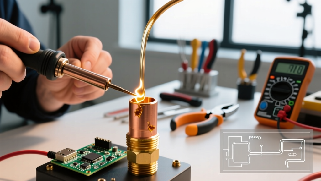
Do not use the solder wire to test the heat at the flame application point. Instead, heat the bottom or side of the coupling with the torch, and touch the solder wire to the top opposite side of the joint. When the solder instantly flashes into a liquid and is sucked into the joint via capillary action, you know the entire thermal mass of the coupling has reached the eutectic point.
Phase 3: Capillary Draw and Solder Feeding
Once the joint is at temperature, remove the flame and feed the solder wire into the seam. The exact amount of solder required is dictated by the joint geometry. For a standard 1/2-inch nominal copper coupling, you need approximately 3/4-inch of 1/8-inch diameter solder wire. For a 3/4-inch coupling, you need roughly 1 inch.
- Underfeeding: Results in a 'starved' joint where solder only penetrates halfway into the coupling cup.
- Overfeeding: Results in excess solder pooling on the outside. While an ugly 'solder blob' on the outside doesn't guarantee a leak, it often masks a starved joint on the inside, as the capillary gap filled up and excess solder was forced out.
Advanced Troubleshooting: Failure Modes and Edge Cases
Even with perfect technique, environmental and material variables can cause joint failure. Here is how to diagnose and correct the most common professional edge cases.
1. The 'Cold Sweat' Joint (Solder Rings but Doesn't Draw)
Symptom: Solder melts and forms a bead around the edge of the coupling but refuses to wick inside.
Root Cause: Moisture inside the pipe. Even a single drop of water trapped upstream will turn to steam when heated. This steam expands and pushes outward, physically blocking the capillary draw of the solder and dropping the internal joint temperature below the melting point of the alloy.
Pro Solution: Use dissolvable bread plugs to dam the water upstream, or purge the line with dry nitrogen at a very low flow rate (1-2 CFH) during soldering. Never attempt to solder a 'weeping' pipe.
2. Flux Carbonization (Burnt Flux)
Symptom: The flux turns into a hard, black or dark green crust, and the solder balls up and rolls off the copper.
Root Cause: Overheating. Standard rosin-based pastes degrade and carbonize at approximately 600°F. Once carbonized, the flux acts as a physical barrier rather than a wetting agent.
Pro Solution: You cannot salvage a burnt joint by adding more solder. You must let the joint cool, disassemble it using two wrenches (to avoid twisting the pipe), mechanically re-sand both surfaces to bare copper, and start over with fresh flux. Consult the Harris Products Group technical expertise hub for specific temperature curves on silver-bearing alloys to avoid burning the flux before the solder melts.
3. Solder 'Bleed-Through' on Thin-Wall (Type M)
Symptom: Solder appears on the inside wall of the pipe, restricting water flow or creating turbulence.
Root Cause: Excessive heat application time on thinner Type M copper, causing the solder's surface tension to break and allowing it to flow past the coupling's internal shoulder.
Pro Solution: Switch to a lower-temperature solder alloy (like 95/5 instead of silver-bearing) and use a pinpoint torch tip to localize heat strictly to the coupling cup, avoiding the pipe entirely.
Final Wipe and Passivation
After feeding the solder, immediately wipe the joint with a damp, 100% cotton rag. This serves two purposes: it shapes the exterior solder bead for a clean, professional finish, and it rapidly quenches the joint, locking the alloy's crystalline structure in place before it can be disturbed by pipe movement. Never use synthetic rags, as the 450°F+ copper will melt polyester fibers directly into the joint surface, creating a permanent cosmetic and structural defect.
Mastering the art of soldering copper couplings is an exercise in thermal discipline. By respecting the capillary gap, managing the thermal mass of the fitting, and understanding the chemical limits of your flux, you will produce joints that easily outlast the 50-year lifecycle of the copper piping itself.