
The Anatomy of a Failed Wire-to-Wire Solder Joint
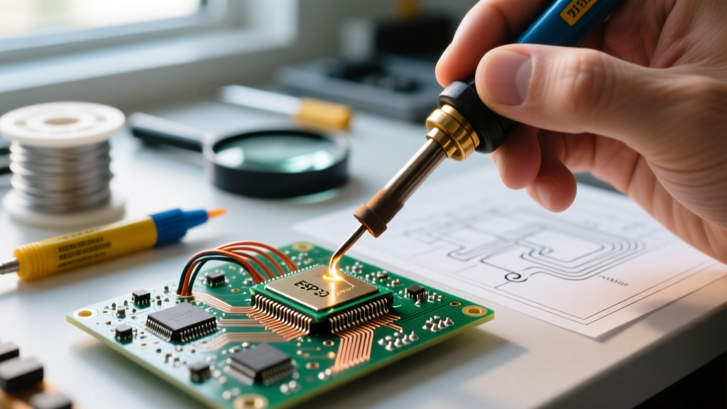
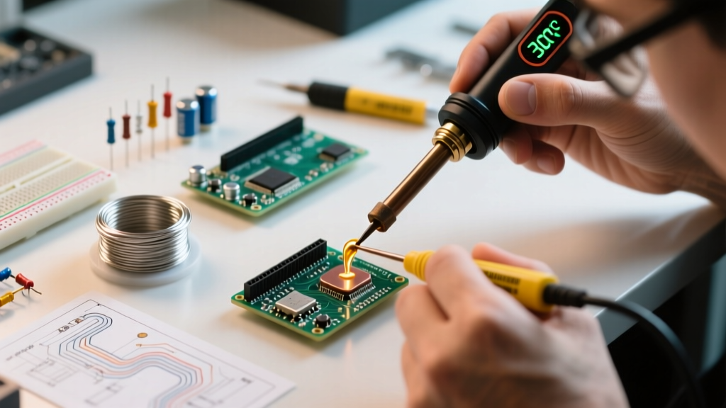
When makers, automotive technicians, and hobbyists ask, "how do i solder two wires together," they are often met with overly simplified tutorials that assume perfect conditions. In the real world, copper oxidizes, flux burns off, and thermal mass varies wildly. Soldering is not merely "gluing" wires with hot metal; it is a complex metallurgical process. A successful joint relies on the formation of an Intermetallic Copper (IMC) layer, specifically Cu6Sn5, which bonds the tin in the solder to the copper in the wire. If your joint fails, the IMC layer is either non-existent (a cold joint) or excessively thick and brittle (heat damage).
In this troubleshooting guide, we bypass the basics and dive straight into the failure modes of wire-to-wire splicing, providing exact thermal profiles and mechanical solutions to ensure your connections survive vibration, thermal cycling, and current loads.
Step-by-Step Diagnostic: Why Your Solder Won't Flow
Before reaching for a higher temperature, you must diagnose the physical symptoms of the failing joint. Here are the three most common scenarios when attempting to join two wires and how to resolve them.
Symptom 1: Solder Balls Up and Refuses to Wet
If your solder forms a perfect sphere and rolls off the copper strands, you are dealing with severe oxidation or a lack of flux activation. Bare copper reacts with oxygen in the air to form copper oxide, a barrier that molten solder cannot penetrate.
The Fix: Do not simply apply more heat. Excessive heat will burn the rosin core out of your solder before it can clean the wire. Instead, mechanically strip the oxidation using a fiberglass scratch pen or fine-grit sandpaper. Next, apply an external, high-activity Rosin-Activated (RA) or water-soluble flux paste to the bare strands before applying the iron. According to the Kester Soldering FAQ, external flux is mandatory when dealing with older or heavily tarnished wire stock.
Symptom 2: The "Cold Joint" (Dull, Grainy, and Brittle)
A cold joint looks like a lumpy, dull gray mass rather than a shiny, smooth concave fillet. This happens when the wires are moved before the solder fully solidifies, or when the iron tip fails to transfer enough thermal energy into the copper's core.
The Fix: The most common mistake is using a needle-like conical tip. Conical tips have a microscopic surface area contact point, resulting in terrible thermal transfer. Switch to a 2.4mm or 3.2mm chisel tip. Furthermore, always pre-tin both wires individually before attempting to join them. Coat each stripped end in solder separately, then press them together and apply the iron to melt the pre-existing solder into a unified mass.
Symptom 3: Wire Insulation Melting Before the Joint Forms
If the PVC or silicone insulation is melting, shrinking, and burning back toward your joint, you are experiencing "heat creep." This is usually caused by leaving a low-wattage iron on the wire for too long, or using a tip that is too small for the wire gauge.
The Fix: Counterintuitively, you must use a larger tip and a slightly higher temperature to complete the joint in under three seconds. A massive bevel or hoof tip acts as a thermal reservoir, dumping heat into the copper instantly so you can remove the iron before the heat travels down the wire to the insulation.
Wire Gauge vs. Iron Temperature Matrix
Matching your thermal profile to the American Wire Gauge (AWG) is critical. The following table assumes the use of Lead-Free solder (SAC305), which requires higher activation temperatures than traditional 60/40 Sn/Pb solder.
| Wire Gauge (AWG) | Recommended Tip Geometry | Optimal Iron Temp (Lead-Free) | Optimal Iron Temp (Sn/Pb) | Dwell Time Limit |
|---|---|---|---|---|
| 24 - 28 AWG | 1.2mm Chisel | 320°C (608°F) | 300°C (572°F) | 1.5 - 2.0 Seconds |
| 18 - 22 AWG | 2.4mm Chisel | 340°C (644°F) | 315°C (600°F) | 2.0 - 3.0 Seconds |
| 14 - 16 AWG | 4.0mm Bevel / Hoof | 360°C (680°F) | 330°C (626°F) | 3.0 - 4.0 Seconds |
| 10 - 12 AWG | 6.0mm Spade / Blade | 380°C (716°F) | 350°C (662°F) | 4.0 - 5.0 Seconds |
Advanced Troubleshooting: Stranded vs. Solid Wire Mismatches
Soldering stranded wire to solid wire introduces a capillary action mismatch. Stranded wire has a high surface area and absorbs solder rapidly via capillary action, while solid wire acts as a massive heat sink that resists wetting. If you simply twist them together and apply solder, the stranded wire will suck up all the flux and solder, leaving the solid wire dry and creating a false joint.
The Protocol:
- Pre-tin the Solid Wire First: Apply the iron to the solid wire and feed solder until a small puddle forms. It requires more time to reach the wetting temperature.
- Pre-tin the Stranded Wire Second: Quickly tin the stranded wire, ensuring the solder wicks no more than halfway up the stripped length to prevent stiffness.
- The Join: Press the tinned stranded wire against the tinned solid wire. Apply the iron to the solid wire side, allowing the heat to bridge the gap and melt both pre-tinned surfaces simultaneously.
Mechanical Reinforcement: Western Union Splice vs. Pigtail
A major point of failure in DIY electronics is the reliance on solder for mechanical strength. Solder is a relatively soft metal and is highly susceptible to fatigue cracking under vibration. The NASA Workmanship Standards explicitly dictate that wires must be mechanically secured before solder is applied.
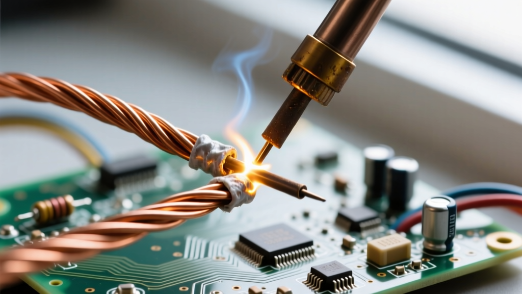
The "Pigtail" splice (twisting the ends together like a candy wrapper) is notorious for snapping at the base of the twist. Instead, utilize the Inline Western Union Splice. To execute this, cross the two stripped wires in an "X" shape, then wrap each end tightly around the opposing wire's straight axis for at least three to four turns. This creates a mechanical lock that will hold even if the solder completely melts, ensuring that a sudden short circuit or thermal event does not result in a disconnected, live wire shorting against a chassis.
Expert Insight: Never use acid-core plumbing solder for electrical wires. The zinc chloride flux will continue to corrode the copper strands long after the joint is made, leading to high-resistance failures and voltage drops months down the line. Always use rosin-core (RMA or RA) or specialized no-clean electronic flux.
Final Verification and Continuity Testing
Once the joint has cooled naturally (never blow on it to cool it down, as this induces micro-fractures in the crystalline structure of lead-free solder), it must be verified. Visually, the solder should form a smooth, concave fillet that contours the wires, with a slight gloss indicating proper flux activation and wetting.
For critical applications, adhere to the IPC-A-610 Standard for acceptability. Perform a gentle "tug test" to verify mechanical integrity, followed by a digital multimeter continuity test. Set your multimeter to the lowest ohms range; a perfect wire-to-wire solder joint should read 0.01 ohms or less. Finally, seal the joint using dual-wall, adhesive-lined polyolefin heat shrink tubing. The inner meltable adhesive layer provides a waterproof seal and acts as a secondary strain relief, preventing the dreaded "solder wick" effect where stiff soldered wire breaks at the boundary of the flexible insulation.