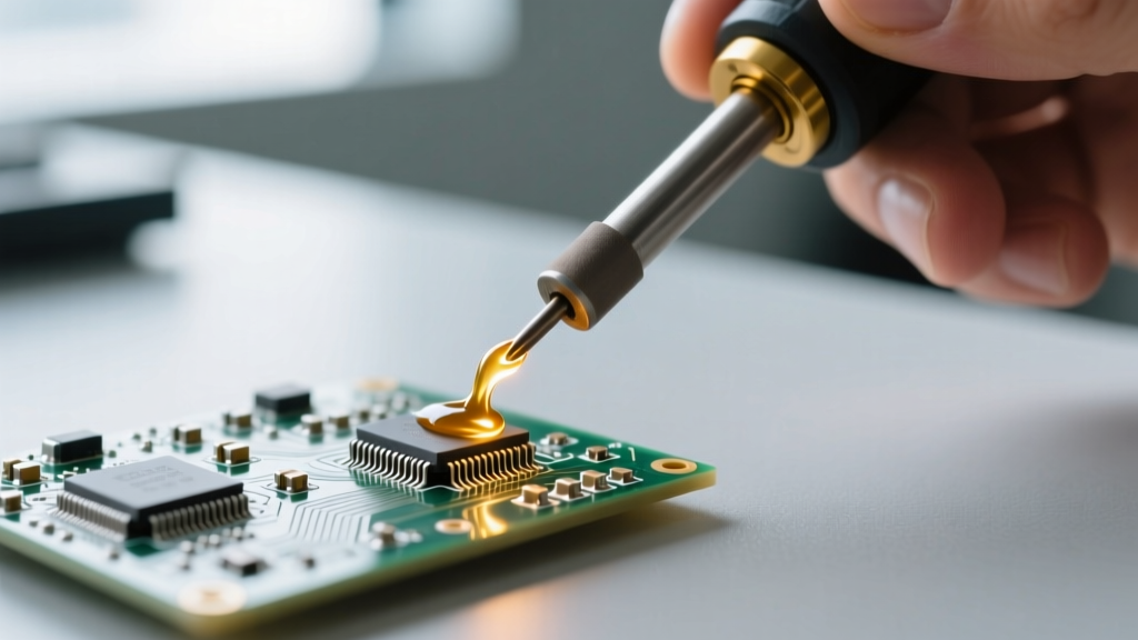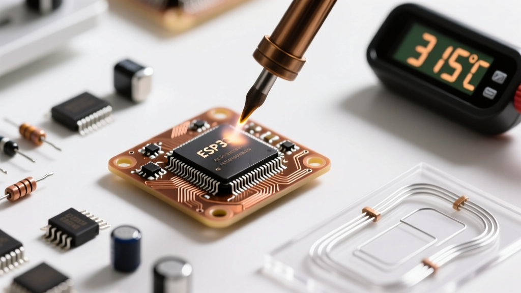

Mastering Thermal Dynamics in PCB Assembly
Setting the correct PCB soldering temperature is not merely a matter of melting solder; it is a precise exercise in thermal management, material science, and operator safety. Whether you are prototyping a simple 555 timer circuit or assembling a dense 6-layer RF board, applying the wrong thermal profile can lead to catastrophic failure modes ranging from micro-fractures in vias to complete pad delamination. In 2026, with the electronics industry heavily standardized around RoHS-compliant lead-free alloys and high-density interconnect (HDI) layouts, understanding the exact thermal limits of your substrates and components is mandatory for producing reliable, IPC J-STD-001 compliant assemblies.
This comprehensive guide breaks down the exact temperature matrices, substrate limits, tooling requirements, and safety protocols necessary to achieve flawless solder joints while protecting both your hardware and your health.
The Core Matrix: Lead vs. Lead-Free Temperature Profiles
A common mistake among hobbyists and junior technicians is setting the soldering station dial to the melting point of the alloy. This guarantees a cold joint. The iron's tip temperature must be significantly higher than the alloy's liquidus point to account for thermal transfer loss when the tip contacts the copper pad and component lead. Below is the definitive reference matrix for the most common alloys used in modern electronics.
| Alloy Composition | Melting Point (Liquidus) | Recommended Iron Temp | Max Dwell Time (Per Joint) | Primary Use Case |
|---|---|---|---|---|
| Sn63/Pb37 (Eutectic) | 183°C (361°F) | 300°C - 320°C | 2 - 3 Seconds | Legacy, Aerospace, Hobbyist |
| SAC305 (Sn96.5/Ag3.0/Cu0.5) | 217°C (423°F) | 350°C - 380°C | 3 - 4 Seconds | Standard RoHS Commercial |
| Sn96.5/Ag3.5 (Lead-Free) | 221°C (430°F) | 360°C - 380°C | 3 - 4 Seconds | High-Reliability RoHS |
| Sn42/Bi57.6/Ag0.4 | 138°C (280°F) | 220°C - 250°C | 2 - 3 Seconds | Low-Temp / Flexible PCBs |
Expert Insight: Never exceed 400°C (752°F) on a standard PCB unless you are using a specialized high-temperature ceramic substrate. Excessive heat does not make the solder flow faster; it merely oxidizes the tip, burns the flux core, and destroys the FR-4 resin.
Substrate Thermal Limits: Understanding FR-4 Tg Ratings
To safely apply heat, you must understand the material receiving it. The standard substrate for PCBs is FR-4, a woven fiberglass cloth with an epoxy resin binder. The critical metric here is the Glass Transition Temperature (Tg)—the point at which the epoxy resin shifts from a rigid, glassy state to a soft, rubbery state.
- Standard Tg (130°C - 140°C): Common in cheap, single-layer prototyping boards. Highly susceptible to warping and pad lifting if exposed to lead-free soldering temperatures (380°C) for more than a few seconds.
- Mid Tg (150°C - 160°C): The baseline for most commercial consumer electronics.
- High Tg (170°C+): Mandatory for lead-free assembly, BGA rework, and high-power applications. The resin maintains structural integrity longer under thermal stress.
When the localized temperature around a copper pad exceeds the substrate's decomposition threshold (typically around 280°C to 300°C for extended durations), the epoxy outgasses. This creates micro-blisters under the copper, leading to pad delamination—a permanent, irreversible failure where the pad lifts entirely off the board. Adhering strictly to the 3-second dwell time rule is your primary defense against Tg-related failures.
Tooling Dynamics: Why Thermal Mass Beats Raw Heat
Amateurs compensate for poor heat transfer by cranking up the temperature. Professionals compensate by increasing thermal mass. A high-wattage station with the correct tip geometry will outperform a generic, high-temperature pencil iron every time.
Station Recommendations & Pricing (2026 Market)
For precision work, closed-loop temperature control is non-negotiable. These stations use thermocouple feedback to inject wattage into the tip precisely when thermal drop-off is detected upon contact with a ground plane.
- Hakko FX-888D (~$115): The undisputed workhorse. Features a 70W ceramic heating element. Pair it with the T18-D24 (2.4mm chisel) tip for optimal thermal transfer on 0805 and SOIC components.
- Weller WE1010NA (~$145): Offers 70W with slightly faster thermal recovery than the Hakko. The ET-B chisel tip is ideal for heavy ground-plane connections.
- Pace ADS200 (~$380): Professional grade. Features an advanced digital interface and interchangeable handpieces, ideal for mixed-technology labs handling both micro-SMD and heavy through-hole connectors.
Rule of Thumb: Always use the largest tip that physically fits the pad. A 600°F conical tip (like the T18-B) has terrible thermal mass and will result in cold joints on large pads. A 600°F chisel tip maximizes surface area contact, transferring heat efficiently at lower dial settings.
Step-by-Step Thermal Execution Protocol
Follow this standardized sequence to ensure optimal wetting and metallurgical bonding without exceeding safety thresholds. This methodology aligns with the NASA Workmanship Standards for high-reliability soldering.
- Prep & Flux: Clean the pad with 99% Isopropyl Alcohol (IPA). Apply a microscopic amount of additional no-clean or RMA liquid flux if working on oxidized legacy boards.
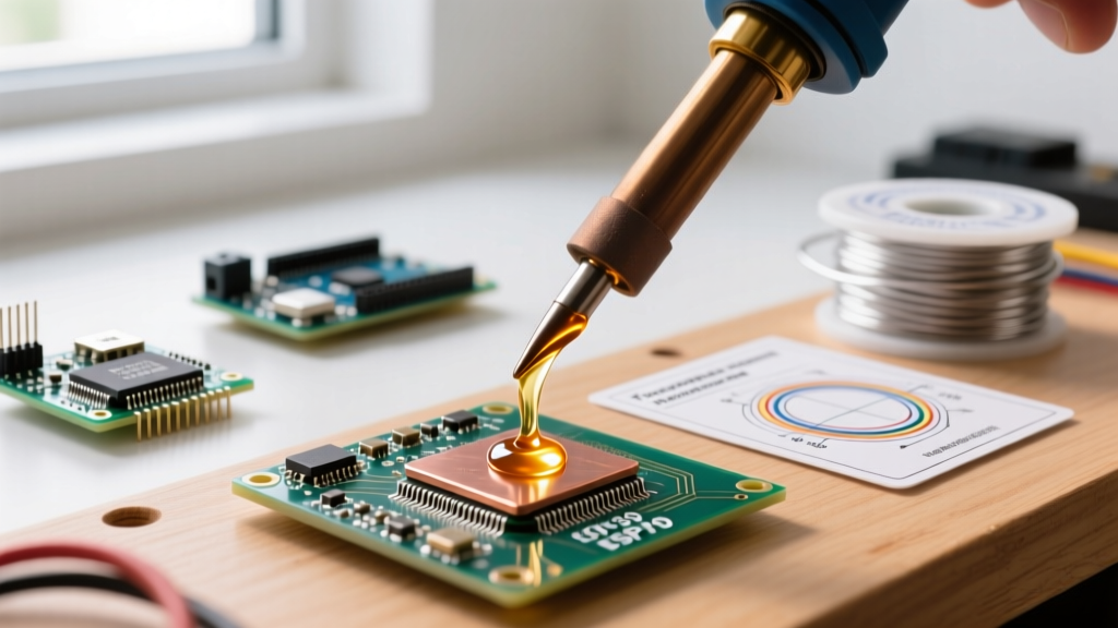
- Tin the Tip: Apply a small amount of solder to the iron tip. This creates a thermal bridge, drastically reducing the time required to heat the joint.
- Simultaneous Contact: Touch the tinned tip to BOTH the component lead and the copper pad simultaneously. Do not melt the solder on the iron and carry it to the joint; the flux will burn off before the joint reaches liquidus.
- Feed the Solder: After 1 second of heating, touch the solder wire to the pad and lead, not the iron tip. If the joint is at the correct temperature, the solder will flash-melt and wick via capillary action.
- Remove & Inspect: Remove the solder wire, then remove the iron. Total dwell time should not exceed 3 to 4 seconds. Allow the joint to cool naturally; blowing on it causes micro-fractures (disturbed joints).
Safety & Fume Mitigation: Protecting the Operator
Thermal safety extends beyond preventing burns; it encompasses respiratory protection. When flux cores (rosin, synthetic, or water-soluble) are subjected to 350°C+, they vaporize into complex aliphatic and aromatic hydrocarbons. Chronic exposure to colophony (rosin) fumes is a known occupational asthmagen.
Furthermore, if you are working with Sn63/Pb37 (leaded solder), OSHA Lead Safety Guidelines dictate strict hygiene protocols. While the soldering temperature (320°C) is far below the vaporization point of lead (1749°C), lead dust transfers from the wire to your fingers, and subsequently to your mucous membranes.
Mandatory Safety Setup
- Fume Extraction: Use an active extraction system with a HEPA and activated carbon filter (e.g., BOFA PrintPRO 3 or Hakko FA-400). Position the intake nozzle exactly 2 to 4 inches from the soldering zone to capture the thermal plume before it reaches your breathing zone.
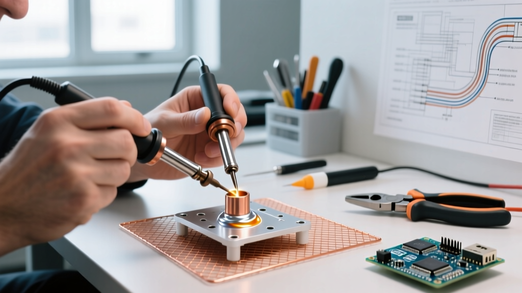
- Thermal Mats: Use a silicone or Kapton thermal mat rated for 500°C+ to protect your workbench from stray iron contact.
- Hygiene: Wash hands with cold water and soap immediately after handling leaded solder. Hot water opens the pores, increasing dermal absorption of heavy metals.
Troubleshooting Thermal Defects
Visual inspection under a 10x loupe or digital microscope will immediately reveal thermal mismanagement.
- Cold Joint (Dull, Grainy, Bulbous): Caused by insufficient heat transfer. The pad or lead did not reach the liquidus temperature before the solder was applied. Fix: Increase tip size, not just temperature. Apply fresh flux and reflow.
- Tombstoning (SMD components standing upright): Caused by uneven heating of the two pads, leading to unequal surface tension pull. Fix: Ensure the iron tip bridges both pads equally, or use a hot air preheater to bring the entire board to 150°C before applying the iron.
- Charred Flux / Blackened Tip: Caused by excessive idle temperature or leaving the iron on the joint for >5 seconds. Fix: Lower station temp to 320°C (leaded) or 360°C (lead-free) and utilize auto-sleep features.
FAQ: Edge Cases in PCB Thermal Management
How do I solder a connector pin attached to a massive ground plane?
Ground planes act as massive heat sinks, pulling thermal energy away from the tip faster than the heater can replenish it. Do not simply turn your iron to 450°C; you will cook the surrounding FR-4. Instead, use a preheater (like a PTC silicone bed) to raise the ambient board temperature to 120°C. This reduces the thermal delta, allowing a 380°C iron to easily push the joint past the liquidus threshold without localized scorching.
Is it safe to use lead-free solder on a vintage Tg130 board?
It is highly discouraged. The 380°C required to properly flow SAC305 will severely stress a standard Tg130 substrate, risking via barrel separation and pad lifting. If you must repair a vintage board, use a low-temperature lead-free alloy like Sn42/Bi57.6 (melting at 138°C), which allows for a safe iron temperature of 220°C, preserving the integrity of the aging epoxy.