
The Metallurgy and Safety Baseline of Wire Splicing
When makers, technicians, and electrical engineers ask how do you solder two wires together, the answer extends far beyond simply melting metal onto copper. A professional solder joint relies on the formation of an Intermetallic Compound (IMC), specifically the Cu6Sn5 layer, which creates a true metallurgical bond rather than a superficial mechanical 'glue.' Achieving this bond reliably requires strict adherence to thermal profiling, flux chemistry, and operator safety.
From a safety perspective, soldering introduces two primary hazards: thermal burns and respiratory sensitization. Pine-based rosin fluxes (colophony), while standard for electronics, release fumes when heated that can trigger occupational asthma and contact dermatitis. According to industrial hygiene guidelines, you should never lean directly over the soldering plume. Always utilize a localized fume extractor, such as the Hakko FA-400, equipped with an activated carbon filter to capture volatile organic compounds (VOCs) and particulate matter before they reach your breathing zone.
The Golden Rule of Flux Chemistry
Never use plumbing-grade acid flux (zinc chloride or hydrochloric acid pastes) on electrical wiring. Acid fluxes are highly corrosive and will cause galvanic corrosion, eventually dissolving the copper strands and creating a high-resistance failure point inside your insulation. Always use a rosin-based (RMA) or no-clean flux core designed specifically for electronics and electrical work, such as the industry-standard Kester 44 series.
Thermal Profiling: Matching Iron Temp to Wire Gauge
One of the most common mistakes when learning how do you solder two wires together is using a one-size-fits-all temperature setting. Wire gauge (AWG) dictates the thermal mass of the joint. If your iron is too cool, the solder will not reflow, resulting in a disturbed or cold joint. If it is too hot, you risk burning the flux core before it can clean the oxidation, vaporizing the flux and leaving a dry, un-solderable copper surface.
Below is a professional thermal profiling chart for standard Sn60Pb40 (60/40 Leaded) and SAC305 (Lead-Free) alloys. These temperatures assume the use of a high-thermal-recovery station like a Weller WE1010 or Hakko FX-888D, not a cheap 40W unregulated stick iron.
| Wire Gauge (AWG) | Solder Diameter | Iron Temp (60/40 Leaded) | Iron Temp (SAC305 Lead-Free) | Typical Application |
|---|---|---|---|---|
| 26 - 22 AWG | 0.5mm - 0.8mm | 320°C (608°F) | 360°C (680°F) | Sensor wires, audio signals, low-current PCB jumpers |
| 20 - 18 AWG | 0.8mm - 1.0mm | 330°C (626°F) | 370°C (698°F) | Automotive accessories, LED strips, standard DC power |
| 16 - 14 AWG | 1.2mm - 1.5mm | 350°C (662°F) | 390°C (734°F) | Appliance wiring, RC battery leads, 15A circuits |
| 12 - 10 AWG | 1.5mm - 2.0mm | 380°C (716°F) | 410°C (770°F) | Main power distribution, solar panels, high-current ESCs |
Step-by-Step: The Western Union Splice Technique
Solder is inherently brittle. It possesses high shear strength but very low tensile strength. If you simply twist two wires together and blob solder over them, any physical pulling will snap the solder joint. To comply with rigorous standards like IPC J-STD-001 and NASA workmanship manuals, the mechanical connection must bear the physical load independently of the solder.
Phase 1: Stripping and Preparation
Use precision wire strippers (such as the Knipex 12 62 180) to remove the insulation without nicking the copper strands. A nicked strand creates a stress concentration point that will eventually fracture under vibration. For a standard splice, strip approximately 1.5 inches (38mm) of insulation from both wire ends. Slide your heat shrink tubing onto one of the wires *before* you begin splicing—a forgotten step that has ruined countless otherwise perfect solder joints.
Phase 2: The Lineman's Splice
- Cross the two stripped wire ends at a 45-degree angle, forming an 'X'.
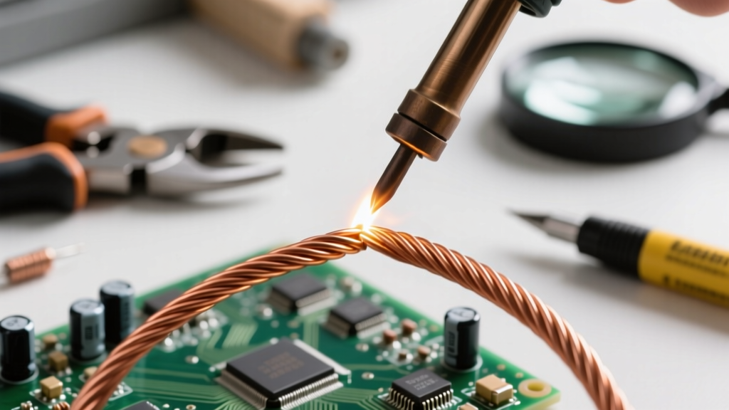
- Wrap the left wire's strands tightly around the right wire's bare copper, making 4 to 5 tight turns.
- Repeat the process with the right wire's strands wrapping around the left wire.
- Use flush cutters to trim the protruding tips of the strands so they are flush with the main wire body. This prevents sharp copper burrs from piercing your heat shrink tubing later.
- Squeeze the splice with pliers to compress the copper strands, maximizing surface area for the solder to wick into.
The Soldering Execution: Capillary Action and Wetting
Now we address the physical act of how do you solder two wires together. The soldering iron's job is to heat the *copper wire*, not the solder.
Expert Insight: Always 'tin' the tip of your iron with a small amount of fresh solder before applying it to the joint. This creates a thermal bridge, transferring heat to the heavy copper mass almost instantly via conduction, rather than relying on poor surface contact.
Apply the tinned iron tip directly to the underside of the Western Union splice. Count to three, allowing the copper to reach the melting point of your alloy. Then, feed the solder wire into the *top* of the splice, directly opposite the iron. If the copper is hot enough, capillary action will violently draw the molten solder deep into the twisted strands. You want to see the solder wick entirely through the joint, leaving a smooth, concave fillet at the edges. A shiny, smooth finish indicates proper wetting; a dull, lumpy finish indicates a cold joint or flux starvation.
Critical Safety Failures and Troubleshooting
Even experienced technicians encounter issues. Here is a diagnostic framework for common wire soldering failures:
- Wicking Under the Insulation: If you apply too much heat for too long, the solder will wick beneath the wire jacket. This turns flexible stranded wire into a rigid, brittle stick that will snap under vibration. Keep your iron contact time under 4 seconds.
- The 'Dry' Joint: If the solder balls up and refuses to flow into the strands, the wire is oxidized or the flux has burned off. Do not add more solder. Remove the iron, clean the joint with 99% isopropyl alcohol, apply external liquid rosin flux, and reheat.
- Disturbed Joints: If the wires move even a fraction of a millimeter while the solder is transitioning from liquid to solid (the plastic phase), the IMC layer fractures. This results in a structurally compromised joint with high electrical resistance. Always use a 'helping hands' tool or silicone wire holders to secure the workpiece.
Insulation and Environmental Protection
A bare solder joint is a short circuit waiting to happen. Electrical tape is unacceptable for professional wire splicing; its adhesive degrades over time, unraveling in high-temperature environments like automotive engine bays or enclosed amplifier chassis.
The Mathematics of Heat Shrink Tubing
For a permanent, waterproof seal, use dual-wall, adhesive-lined polyolefin heat shrink tubing with a 3:1 shrink ratio. Brands like 3M EPS300 or DSG-Canusa feature an inner layer of polyamide hot-melt adhesive. When heated, the outer wall shrinks while the inner adhesive melts, filling the voids between the solder joint and the wire insulation, creating a hermetic environmental seal.
To size your tubing correctly, measure the outer diameter (OD) of your wire's insulation. Multiply that number by 1.2 to allow room for the tubing to slide over the bulky solder joint, but ensure it is less than 3x the tubing's expanded diameter so it clamps down tightly on the wire jacket. Slide the tubing over the joint, ensuring at least 0.5 inches of overlap onto the original wire insulation on both sides. Apply heat evenly with a heat gun set to 250°C (482°F) until you see a small bead of adhesive squeeze out of the ends, confirming a watertight seal.
References and Further Reading
Mastering how do you solder two wires together requires continuous refinement of your technique. For deeper dives into industry standards and practical applications, consult the following authoritative resources:
- IPC J-STD-001 Requirements for Soldered Electrical and Electronic Assemblies - The definitive global standard for soldering criteria and defect classification.
- Adafruit Guide to Excellent Soldering - An outstanding visual and practical guide for makers transitioning to professional-grade techniques.
- Kester 44 Rosin Flux Technical Data Sheet - Essential reading for understanding the chemical activation temperatures of your solder's flux core.