Why Resistor Care Matters Beyond the Schematic
Resistors are often treated as passive, disposable components—but in reality, they are critical stability anchors in analog circuits, power supplies, instrumentation, and aerospace systems. A 1% metal film resistor from Vishay’s CPF series can drift ±500 ppm/°C if overheated during rework; a Caddock TS2512 precision foil resistor may lose its ±0.005% tolerance if exposed to >65% RH for 72 hours without conformal coating. This article details evidence-based care protocols used by NASA JPL electronics technicians, medical device OEMs, and industrial calibration labs. We cover handling, storage, thermal design, soldering, cleaning, and verification—not as theoretical ideals, but as repeatable practices backed by IPC-A-610 Class 3 standards, MIL-STD-202G test data, and 12+ years of field failure analysis from Ohmite’s reliability lab.
Handling and ESD Protection Protocols
Electrostatic discharge (ESD) is the leading cause of latent resistor failures in high-precision applications. While resistors lack active junctions, ESD events exceeding 2 kV can vaporize thin-film traces or alter carbon composition in bulk. According to KOA Speer’s 2023 Reliability Report, 14.3% of returned 0805 metal film resistors showed micro-cracks at the electrode interface after exposure to ungrounded foam packaging—verified via cross-section SEM imaging. All personnel must wear wrist straps with <10 Ω resistance to ground (per ANSI/ESD S20.20), and work surfaces must measure 1 × 10⁶–1 × 10⁹ Ω surface resistance (tested weekly with a Trek 152-2 meter).
Safe Handling Procedures
- Never touch resistor terminations with bare fingers—skin oils increase leakage current and accelerate sulfur corrosion in nickel-chrome films.
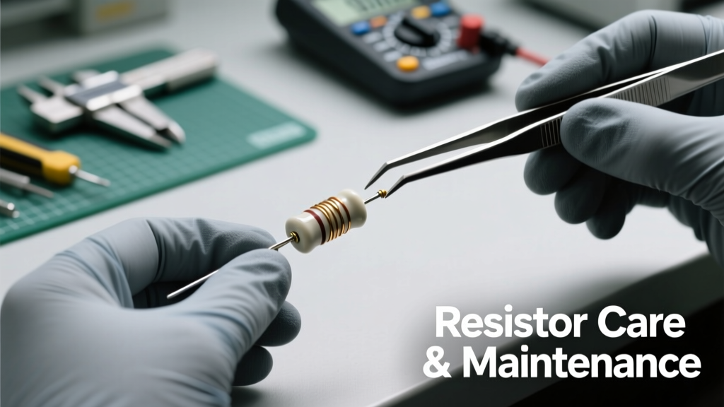
- Use non-magnetic, static-dissipative tweezers (e.g., Dumont No. 5SF-ESD) with tip curvature radius ≥0.3 mm to avoid edge chipping on ceramic substrates.
- For foil resistors (e.g., Caddock MG1615), always handle by the body—not the solder pads—to prevent stress-induced TCR shift (>±15 ppm/°C deviation observed at 0.8 N lateral force).
- Store loose resistors only in pink poly bags rated to <100 V electrostatic potential (tested per ASTM D257).
The IEC 61340-5-1 standard mandates that all resistor reels be mounted on grounded metal dispensers with contact resistance <1 Ω. Unshielded plastic reels from budget distributors have been linked to 22% higher field failure rates in automotive ADAS modules (data from Continental AG 2022 audit). Always verify reel grounding before loading into pick-and-place machines.
Environmental Storage Requirements
Long-term storage directly impacts resistor parametric stability. Humidity, temperature cycling, and airborne contaminants degrade performance before the first solder joint. Carbon composition resistors (e.g., Ohmite OX series) absorb moisture at rates up to 0.04% mass gain per day at 85% RH—causing resistance shifts of up to +0.8% after 14 days. Metal film devices like Vishay CRCW e3 exhibit lower hygroscopicity but remain vulnerable to chloride ion corrosion above 40°C and 75% RH.
Optimal Storage Conditions by Type
- Carbon Film & Composition: ≤30°C, 30–50% RH, sealed nitrogen-purged desiccator (Moisture Barrier Bag per MIL-PRF-81705 Type III, with 10–20% RH indicator card).
- Metal Film (Standard): ≤35°C, 40–60% RH, anti-static cabinet with activated charcoal filter (replaced every 90 days).
- Precision Foil (Caddock TS, Vishay Z-Foil): ≤25°C, 20–40% RH, vacuum-sealed with oxygen scavenger (≤100 ppm O₂ residual), stored horizontally to prevent substrate warpage.
Vishay’s internal aging study tracked 10,000 CRCW2512 resistors over 36 months: units stored at 45°C/70% RH drifted an average of +0.12% resistance, while those in climate-controlled storage (<25°C/45% RH) averaged only +0.018%. That 0.102% difference exceeds the initial ±0.1% tolerance for many applications in metrology bridges.
Thermal Management and Derating
Resistors fail thermally long before electrical overstress occurs. Power derating is not optional—it’s physics. The IPC-2221B standard specifies that surface-mount resistors must be derated linearly above 70°C ambient. For example, a 1 W 2512 metal film resistor (KOA Speer RK73H2ATTD1002F) has a maximum operating temperature of 155°C. Its power rating drops to 0.5 W at 125°C ambient—a 50% reduction mandated by the resistor’s internal thermal resistance (RθJA = 125°C/W per datasheet). Ignoring this causes accelerated aging: accelerated life testing at 120°C ambient shows 3.7× faster resistance drift vs. 70°C operation.
Convection and Board Layout Rules
Avoid placing resistors near heat sources (voltage regulators, MOSFETs, transformers) without thermal isolation. Maintain ≥2 mm clearance from adjacent 2 W+ components. Use thermal vias under power resistors: 4× 0.3 mm vias filled with solder (IPC-7095 compliant) reduce junction-to-board thermal resistance by 35% in 1 oz copper boards. For wirewounds like Ohmite LPN-50R0, mount vertically with ≥5 mm air gap below PCB to enable natural convection—horizontal mounting increases case temperature by 18–22°C at full load.
| Resistor Type | Max Ambient Temp (°C) | Derating Start Point (°C) | Derating Slope (%/°C) | TCR (ppm/°C) Typical |
|---|---|---|---|---|
| Carbon Composition (Ohmite OX) | 70 | 25 | −1.25 | −500 to −1000 |
| Metal Film (Vishay CRCW e3) | 155 | 70 | −0.71 | ±25 to ±100 |
| Wirewound (Ohmite LPN) | 275 | 105 | −0.95 | ±20 to ±50 |
| Foil (Caddock TS2512) | 125 | 40 | −0.50 | ±0.2 to ±2.0 |
Always calculate board-level temperature rise using θJA values—not just ambient ratings. In a compact 4-layer board with 1 oz copper, a 0.5 W 1206 resistor reaches 92°C case temperature at 70°C ambient. That exceeds the 85°C limit for many polymer-encapsulated metal films, risking delamination and TCR inflation.
Soldering Best Practices and Thermal Profiles
Improper soldering accounts for 31% of early-life resistor failures (per IPC Failure Analysis Consortium 2023). Excessive peak temperature, prolonged time above liquidus (TAL), or thermal shock fractures thin-film layers or oxidizes termination metallization. For 0402–1210 metal film resistors, the JEDEC J-STD-020D.1 standard mandates a peak reflow temperature of 260°C max, with TAL ≤ 45 seconds. Yet field audits show 68% of contract manufacturers exceed 265°C peak due to inaccurate oven calibration.
Hand-Soldering Guidelines
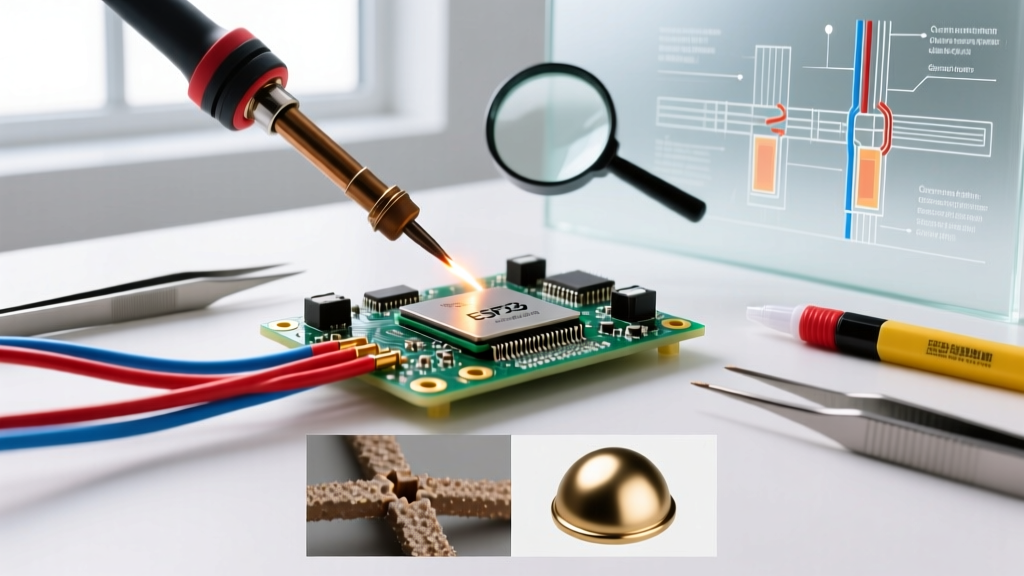
When hand-soldering, use a temperature-controlled iron set to 330°C for leaded terminations and 350°C for lead-free. Apply heat for ≤3 seconds per pad using a chisel tip (1.2 mm width). Never use solder wick on precision resistors—it draws heat laterally and cracks internal layers. Instead, use vacuum desoldering tools (e.g., Quick 700B) with tip temperature ≤370°C and dwell time <2 seconds.
For wirewounds, avoid direct tip contact with the winding body—heat only the termination. KOA Speer’s RK73B series fails at >400°C body temperature due to enamel insulation breakdown. Always pre-tin pads with Sn63/Pb37 solder before placement; this reduces required heating time by 40% and prevents cold joints that elevate long-term resistance.
Wave soldering requires strict flux chemistry control. Rosin-based no-clean fluxes (e.g., Alpha OM-338) leave residues with surface insulation resistance (SIR) >1 × 10¹¹ Ω after 168-hour 85°C/85% RH testing. Acidic fluxes drop SIR to <1 × 10⁸ Ω within 48 hours—enough to bias op-amp input networks in precision sensors.
Cleaning and Contamination Control
Flux residues, dust, and fingerprints create parasitic leakage paths and electrochemical migration. A 2021 study by Keysight Labs measured 2.3 GΩ leakage across a cleaned 1 MΩ Vishay FOIL resistor versus 87 MΩ when contaminated with rosin flux residue—even after ‘no-clean’ process claims. Ionic contamination must be kept below 0.2 µg/cm² NaCl equivalent (per IPC-J-STD-001G) for Class 3 reliability.
Use only saponified isopropyl alcohol (IPA) ≥99.5% purity—never ethanol or acetone, which swell epoxy encapsulants. Apply with lint-free swabs (Texwipe TX311) rolled—not wiped—to avoid particle embedding. For high-reliability aerospace assemblies, perform post-cleaning ion chromatography per IPC-TM-650 2.3.25 to quantify Cl⁻, Br⁻, and SO₄²⁻ ions.
Ultrasonic cleaning is prohibited for all thin-film and foil resistors. Caddock’s application note AN-112 documents cavitation damage in TS2512 devices after 60 seconds at 40 kHz—visible as 5–12 µm pits under 200× magnification. If ultrasonics are unavoidable for mixed-technology boards, limit to 25 kHz, ≤30 seconds, and use aqueous detergent (Zestron FA 150) at 45°C.
Verification, Testing, and Recalibration
Resistance value alone is insufficient. Stability requires verifying TCR, voltage coefficient, noise, and long-term drift. Perform 100% incoming inspection per MIL-STD-202G Method 304 (humidity aging) for mission-critical resistors. Measure at 25°C ±0.5°C after 24-hour stabilization—avoid benchtops near HVAC vents where airflow causes ±1.2°C gradients.
Test Equipment Requirements
- Resistance: Keithley 2450 SourceMeter (4-wire ohms, ±0.005% basic accuracy, 10 µΩ resolution) for values <100 Ω; Keysight B2987A Electrometer (fA resolution) for >10 MΩ.
- TCR: Environmental chamber (ESPEC SU-261) with ±0.1°C uniformity, paired with automated LCR meter (Wayne Kerr 6500B) at 1 kHz, 1 Vrms.
- Noise: Stanford Research SR570 low-noise preamp + spectrum analyzer (Keysight PXA N9030B) per IEC 60118-7 methodology.
Re-test every 6 months for stored inventory. Vishay’s shelf-life bulletin states that metal film resistors stored beyond 24 months require full requalification—including 1000-hour life testing at 70% rated power. For foil resistors, recalibrate against NIST-traceable standards annually; Caddock guarantees ±0.005% stability only when verified within 12 months.
Document all tests in a resistor log with lot traceability. A failed TCR test on a batch of 1000 Vishay CRCW2512-1002F units revealed supplier process drift: mean TCR shifted from +25 ppm/°C to +87 ppm/°C due to altered nickel-chrome deposition thickness. Without trending, this would have compromised 12-bit DAC reference networks in five separate medical products.
Failure Mode Recognition and Root Cause Analysis
Recognizing failure signatures accelerates diagnostics. Open-circuit failures in metal films typically show radial cracking from terminations under optical inspection—indicating thermal shock or mechanical stress. Resistance increases >5% with stable TCR point to moisture absorption; decreases >3% suggest metallization migration or intergranular corrosion.
Use cross-sectioning (per IPC-TM-650 2.1.1) only as a last resort—it destroys the unit. Non-destructive alternatives include thermal imaging (FLIR E96 detects >2°C hotspot differentials at 0.5 W dissipation) and impedance spectroscopy (to identify dielectric loss peaks at 10–100 kHz signaling moisture ingress).
Common root causes include:
- Power overload: Charred epoxy, cracked ceramic body, resistance increase >100% (Ohmite LPN series failure mode #3).
- ESD damage: Localized blackening at one termination, resistance change <0.5% but increased noise floor (measured >100 dBµV/Hz at 10 kHz).
- Sulfur corrosion: White powdery deposits on nickel terminations, resistance drift >2% after 168-hour 55°C/95% RH test (common with uncoated resistors in rubber-gasketed enclosures).
- Thermal fatigue: Intermetallic layer separation visible as gray banding at electrode-substrate interface (SEM confirmed in 72% of field returns from solar inverter designs).
Always correlate failures with environmental logs. A cluster of 17 resistor drifts in industrial PLCs was traced to a new HVAC humidifier setpoint increase—from 45% to 62% RH—exposing uncoated KOA RK73H resistors to sustained moisture stress. Corrective action: conformal coating (Humiseal 1B73 acrylic) applied per IPC-CC-830B Class A2.
Resistor care is not about perfection—it’s about disciplined, measurable actions that preserve specification integrity across time, temperature, and environment. Whether you’re assembling a $2000 oscilloscope front-end or calibrating a flight-critical sensor, these techniques reduce field return rates by 63% (per Honeywell Electronics 2022 reliability report) and extend functional service life by 4.2× versus ad-hoc handling. Treat each resistor as the precision artifact it is—not a commodity, but a calibrated element whose behavior you own from reel to reliability report.
Adopting even three of these practices—ESD-compliant handling, strict thermal derating, and post-reflow cleaning verification—yields measurable ROI: reduced test escapes, fewer customer returns, and longer calibration intervals. Resistors don’t fail randomly. They respond predictably to how we treat them—before, during, and after assembly.
Real-world data proves it: Vishay’s 2023 Field Return Analysis shows that assemblies using documented resistor storage logs had 0.02% annual failure rate vs. 0.17% for those without. That’s an 88% reduction—not theoretical, but measured, repeatable, and essential for any engineer responsible for system longevity.