
The Anatomy of a Perfect Wire-to-Wire Solder Joint
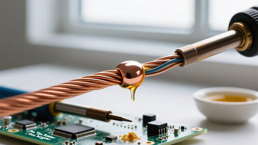
When professionals need to solder two wires together, they are not merely melting metal to act as a glue. A proper solder joint is a complex metallurgical bond. When molten solder contacts the copper strands, a chemical reaction forms an Intermetallic Compound (IMC) layer—specifically Cu6Sn5 and Cu3Sn. This microscopic layer, ideally between 1 and 2 microns thick, is what provides the electrical conductivity and mechanical strength of the joint. If the temperature is too low, the IMC layer fails to form, resulting in a weak, high-resistance connection. If the temperature is too high or applied for too long, the IMC layer grows excessively thick, becoming brittle and prone to fracturing under vibration. Understanding this metallurgical reality is the first step toward mastering professional wire splicing.
Pre-Soldering: Mechanical Preparation & Wire Stripping
Before you even turn on your soldering station, the physical preparation of the wire dictates the success of the joint. The goal is to expose the exact length of bare copper required for the splice without damaging the underlying strands.
Gauge-Specific Stripping Tolerances
Using the wrong stripping technique can nick the copper strands. A single nick on an AWG 18 wire can reduce its tensile strength by up to 20% and create a localized hot-spot under high current loads. Professionals avoid cheap automatic wire strippers that use aggressive blades. Instead, use precision thermal strippers for aerospace-grade wire, or high-quality manual strippers like the Ideal Industries 45-122 calibrated to the exact AWG. For a standard Western Union splice, the strip length should be roughly 1.5 to 2 inches (38-50mm) for wires between AWG 22 and AWG 14. Ensure the copper is bright and free of oxidation; if the wire is old, lightly abrade the strands with a fiberglass scratch pen before tinning.
The Western Union vs. Pigtail Splice: Choosing the Right Joint
Not all wire splices are created equal. The mechanical joint you choose must match the environmental and physical demands of the application. Below is a professional decision matrix for selecting the correct splice when you need to solder two wires together.
| Splice Type | Tensile Strength | Profile / Bulk | Best Application |
|---|---|---|---|
| Western Union (Lineman's) | Extremely High | Linear, Moderate | In-line harnesses, high-vibration environments, structural wiring. |
| Pigtail (Twist) | Low | Compact, Bulbous | Enclosed junction boxes, low-stress LED connections, prototyping. |
| Hook Splice | Moderate | Linear, Thin | Solid-core wires, quick breadboarding, low-current signal lines. |
| Mesh / Braided | High | Thick, Heavy | High-current AWG 10+ battery cables, ground straps. |
For the vast majority of professional in-line wiring harnesses, the Western Union splice (also known as the Lineman's splice) is the gold standard. To execute it, cross the stripped wires over each other about one-third of the way from the insulation, then twist the shorter end around the longer end 3 to 4 times. Repeat for the other side. This creates a joint that can withstand significant pulling force even before solder is applied.
Thermal Management: Tinning and Heat Transfer
The most common mistake amateurs make is twisting the bare wires together and then holding a blob of solder against the iron tip, hoping it will melt into the joint. This causes flux burnout and cold joints. The professional methodology requires pre-tinning.
The Pre-Tinning Protocol
First, slide your heat shrink tubing onto one of the wires (a surprisingly common step to forget). Next, apply a small amount of flux to the bare strands of both individual wires. Using a chisel tip (such as the Hakko T18-D24) set to 320°C for Sn63/Pb37 (leaded) solder or 360°C for SAC305 (lead-free), tin each wire separately. The solder should wick effortlessly into the strands via capillary action. Once both wires are tinned, hook them together (if using a Western Union splice) and apply the iron directly to the copper mass. The pre-existing solder on both wires will reflow and merge seamlessly. This technique guarantees complete wetting and minimizes the time the iron spends on the wire, preventing the insulation from melting.
Flux Chemistry: Why Rosin-Core Isn't Always Enough
While rosin-core solder wire contains flux, it is often insufficient for heavy-gauge wires or oxidized copper. Professional technicians supplement the core flux with an external, high-activity rosin flux. Kester 186 Flux is a legendary mildly activated rosin (RMA) flux that breaks down copper oxides instantly upon heating. When soldering two wires together in harsh or humid environments, applying a dab of RMA flux paste ensures the solder flows like water. Remember that RMA fluxes leave a conductive residue if exposed to moisture over time; therefore, cleaning the joint with 99% isopropyl alcohol and an acid brush before applying heat shrink is a mandatory professional step.
Post-Soldering Inspection and Heat Shrink Application
According to the stringent criteria outlined in NASA-STD-8739.3 for workmanship, a soldered wire joint must exhibit a smooth, shiny fillet with visible wetting angles. The solder should not completely wick under the wire insulation, as this creates a rigid point of stress concentration that can snap the wire during bending.
For insulation, professionals shun standard single-wall heat shrink. Instead, use dual-wall, adhesive-lined polyolefin heat shrink (such as 3M EPS300). When heated, the inner thermoplastic adhesive melts and flows into the crevices of the solder joint and the wire insulation, creating a 100% waterproof and strain-relieved seal. Apply heat from the center of the tubing outward to push excess adhesive out the ends, ensuring no air pockets remain trapped inside.
Troubleshooting Common Wire Soldering Failures
Even experienced technicians encounter anomalies. Here is how to diagnose and rectify the most frequent failure modes when you solder two wires together:
- Cold Joints (Grainy/Dull Appearance): Caused by insufficient heat or moving the wire before the solder solidifies. Fix: Re-flux the joint and reheat with a higher wattage iron or a wider tip to ensure the entire copper mass reaches the liquidus temperature.
- Solder Wicking Under Insulation: Occurs when the iron is held on the wire too long, or the wire is stripped too far. Fix: Use a heat sink (like a pair of hemostats) clamped between the joint and the insulation to absorb excess thermal energy.
- Burnt Flux Residue (Black/Charred): Indicates the iron temperature is excessively high, destroying the flux before it can clean the metal. Fix: Lower the station temperature by 20°C and rely on a larger tip mass for heat transfer rather than raw temperature.
"The reliability of a soldered harness is defined not by the amount of solder applied, but by the quality of the metallurgical wetting and the mechanical strain relief provided post-solder." — Adapted from IPC J-STD-001 requirements for soldered electrical assemblies.
By respecting the metallurgy, preparing the mechanical joint properly, and managing your thermal profile, you will produce wire-to-wire solder joints that survive decades of vibration, thermal cycling, and current load.