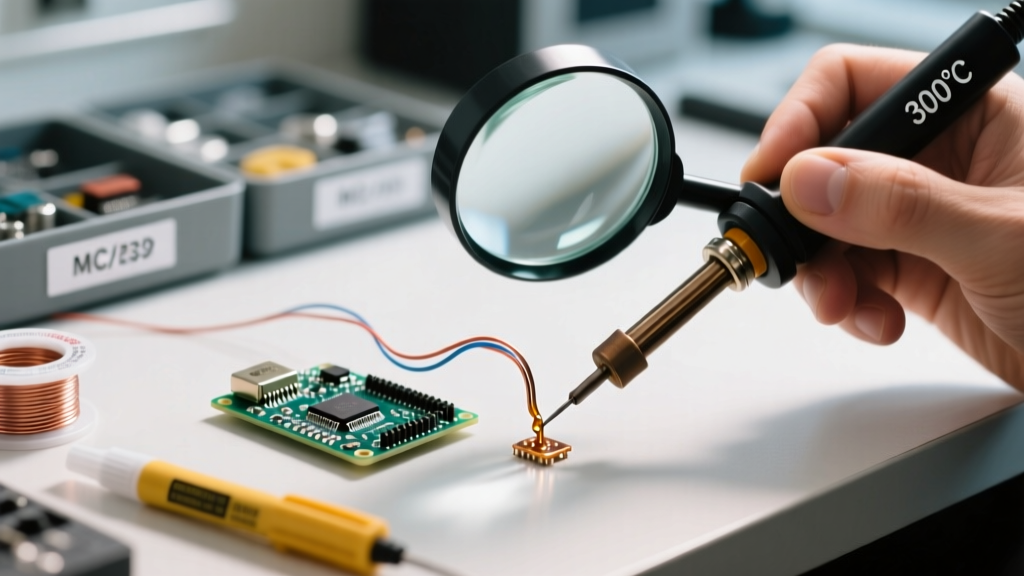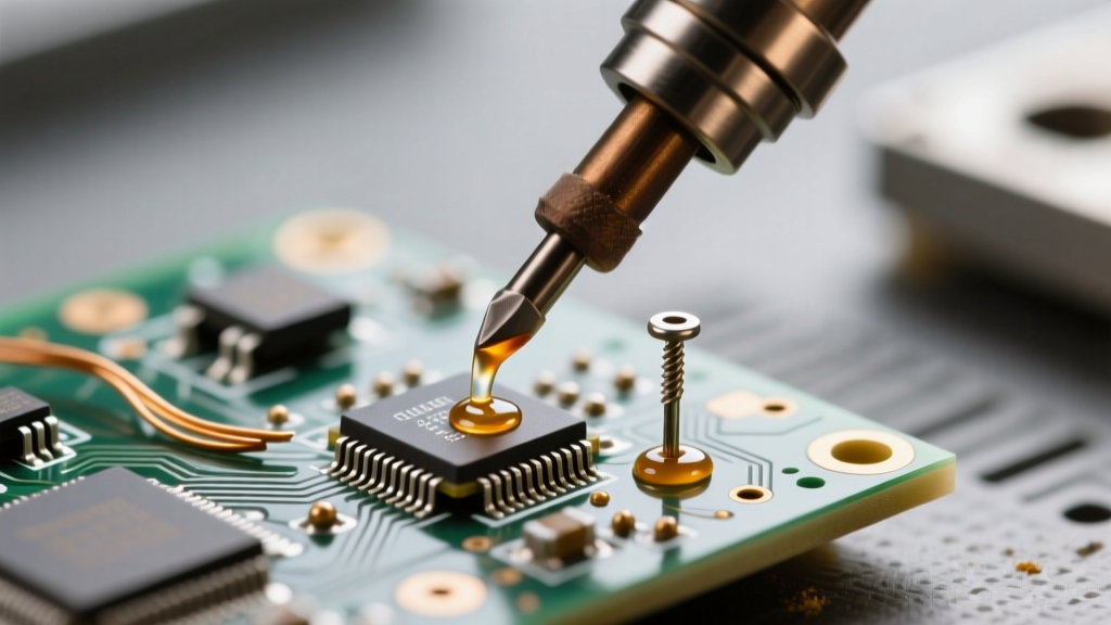

Removing components from a printed circuit board (PCB) is inherently more destructive than soldering them. When you solder, you are building a metallurgical bond; when you desolder, you are fighting the physical limits of the board's substrate, the component's thermal mass, and the plated through-holes (PTH). Amateurs often walk away with lifted pads, cracked vias, or destroyed silicon. Professionals, however, rely on metallurgical manipulation and strict thermal management to salvage both the board and the component.
The Physics of Pad Lift: Why Amateurs Fail
Pad lift is the ultimate failure mode in rework. It occurs when the epoxy resin binding the copper cladding to the fiberglass weave degrades. Standard FR-4 material has a Glass Transition Temperature (Tg) between 130°C and 140°C. High-Tg boards push this to 170°C. Once the localized temperature exceeds the Tg, the epoxy softens, and the Z-axis Coefficient of Thermal Expansion (CTE) spikes dramatically—from roughly 50 ppm/°C to over 250 ppm/°C.
This violent Z-axis expansion does two things: it rips the copper pad away from the substrate, and it stretches the copper barrels inside PTH vias until they micro-crack. According to the NASA Workmanship Training Manual, excessive heat application during rework is the primary culprit for internal barrel cracking. To prevent this, professionals do not simply apply more heat; they manage the thermal delta and reduce the time the board spends above Tg.
Tool Arsenal: Solder Suckers vs. Desoldering Stations vs. Braid
Choosing the right extraction tool depends entirely on the component's thermal mass and the board's layer count. A manual solder sucker (like the Edsyn Soldapult) relies on mechanical shock and rapid cooling, which can snap brittle component leads. Copper braid (desoldering wick) relies on capillary action but requires prolonged iron contact, increasing the risk of pad lift on delicate surface-mount pads. For professional through-hole extraction, a dedicated pneumatic or electric desoldering station, such as the Hakko FR-301, is mandatory. These tools feature a hollow tip connected to a vacuum pump, allowing you to melt the solder and extract it in a single, fluid motion without mechanical shock.
| Method | Best Application | Thermal Risk | Professional Verdict |
|---|---|---|---|
| Manual Solder Sucker | Single-layer DIY boards | Low (but high mechanical shock) | Avoid for precision or multi-layer PCBs. |
| Copper Braid (Wick) | SMD pads, QFP/QFN cleanup | High (prolonged iron contact) | Essential for final pad leveling, not bulk removal. |
| Electric Desoldering Station | Multi-layer PTH, high thermal mass | Medium (rapid extraction) | The gold standard for through-hole rework. |
| Hot Air Rework Station | Multi-pin SMD, BGAs | Medium (broad area heating) | Requires Kapton shielding and precise airflow. |
Advanced SMD Removal: The Low-Temp Alloy Method
When removing large SMD components like QFP-144 microcontrollers or SOIC-16 drivers, using a standard hot air gun or iron risks overheating the silicon die. The professional workaround is metallurgical manipulation using low-temperature alloys, such as Chip Quik (Sn42/Bi57/Ag1). Standard lead-free solder (SAC305) melts at 217°C, and eutectic leaded solder (Sn63/Pb37) melts at 183°C. Chip Quik melts at a mere 58°C.
By flooding the existing SMD joints with this bismuth-based alloy, you create a mixed-metal eutectic that remains liquid at temperatures far below the board's Tg. You can then use a standard hot air station set to 150°C—or even a low-wattage iron—to lift the component off the board with tweezers while the solder is still fully molten. This completely eliminates the risk of pad lift and prevents thermal damage to the component's internal wire bonds. When using hot air, always shield adjacent components with Kapton tape and aluminum foil tape. The foil reflects convective heat, while the Kapton provides a secondary thermal barrier. Set your airflow to a moderate 30-40% to prevent blowing small passive components (like 0402 resistors) off the board. For deeper insights into SMD rework profiles, SparkFun's Desoldering Guide offers excellent baseline temperature profiles.
Through-Hole Mastery: Managing Thermal Mass on Multi-Layer PCBs
Desoldering a TO-220 voltage regulator or a heavy electrolytic capacitor from a 4-layer or 6-layer PCB is notoriously difficult. The internal ground and power planes act as massive heat sinks, wicking thermal energy away from the joint faster than a standard 60W iron can supply it. Amateurs respond by turning their iron up to 450°C and holding it against the joint for 30 seconds. This guarantees catastrophic pad lift.
The Pre-Heating and Pre-Feed Flux Technique
Professionals use a dual approach. First, the board is placed on a PTC pre-heater (like the Hakko FR-810B) and brought up to a uniform 110°C. This reduces the thermal delta the desoldering iron must overcome. Second, old factory solder is heavily flux-depleted and oxidized. Before applying the desoldering tip, you must 'pre-feed' the joint with fresh, highly active flux—such as Kester 951 liquid flux or Amtech NC-559-V2-TF tacky flux—and add a touch of fresh, thick solder wire. This fresh solder acts as a thermal bridge, transferring heat from the hollow desoldering tip into the core of the PTH via in seconds, allowing the vacuum pump to clear the hole cleanly on the first trigger pull.
Post-Desoldering Cleanup and Pad Remediation
Once the component is removed, the pads will be oxidized and contaminated with carbonized flux residue. Do not scrape the pads with a scalpel; this will gouge the copper and compromise the surface finish (ENIG or HASL). Instead, use a stiff brass wire brush or a fiberglass scratch pen combined with 99% isopropyl alcohol to gently polish the pads back to a bright metallic finish.
If a pad has partially lifted during the extraction process, the IPC J-STD-001 Standard outlines specific repair procedures. Minor lifting can sometimes be stabilized using high-temperature epoxy (like Loctite 4981) to re-bond the copper to the FR-4 substrate before installing the replacement component. For completely severed pads, professionals will scrape back the solder mask on the connected trace, tin the exposed copper, and use a 30 AWG polyimide-coated copper wire to create a microscopic jumper to the component lead.
Pro Tip on Via Preservation: When clearing a PTH via with a desoldering station, never use the metal cleaning pin to forcefully punch through cooling solder. The copper barrel is highly susceptible to mechanical deformation when hot. Always use a properly sized, heat-resistant silicone or Teflon cleaning tool, and only insert it while the solder is fully molten and the vacuum is actively pulling air through the barrel.