
The Great Misnomer: Deconstructing 'Brazing and Soldering Welding'
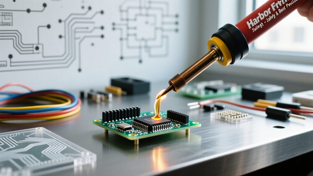
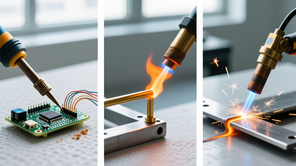
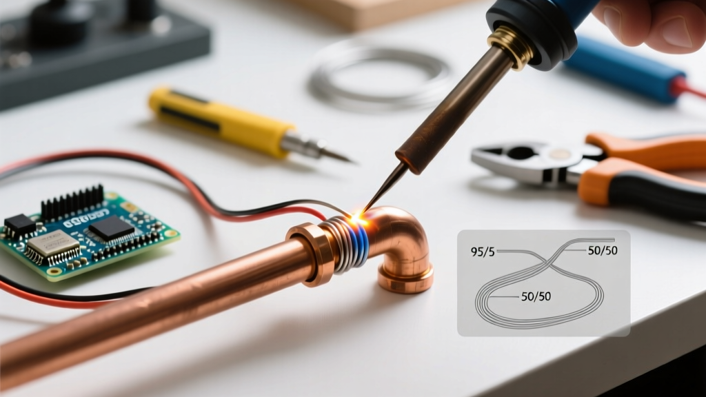
When professionals and advanced hobbyists discuss metal joining, the phrase brazing and soldering welding frequently surfaces in search queries and workshop debates. However, from a strict metallurgical standpoint, this phrase is a contradiction. True welding involves the melting and fusion of the base metals themselves, often with a filler material, to create a continuous grain structure across the joint. Brazing and soldering, conversely, rely on capillary action and adhesion without ever reaching the melting point of the base materials.
Understanding this distinction is not just academic pedantry; it fundamentally dictates your heat management strategy, joint design, flux selection, and filler alloy chemistry. In 2026, with advanced lead-free solders and specialized silver-brazing alloys dominating the market, treating these processes as mere 'low-temperature welding' is a fast track to catastrophic joint failure, thermal shock, and base metal annealing. This guide provides professional-grade frameworks for mastering these distinct capillary joining techniques.
Thermal Thresholds and Metallurgical Bonds
The dividing line between soldering and brazing is universally recognized by the American Welding Society (AWS) and global metallurgical standards at 840°F (450°C). Below this threshold, you are soldering; above it, you are brazing. Both processes require the base metal to be heated above the liquidus temperature of the filler alloy, allowing the molten filler to be drawn into the joint via capillary action.
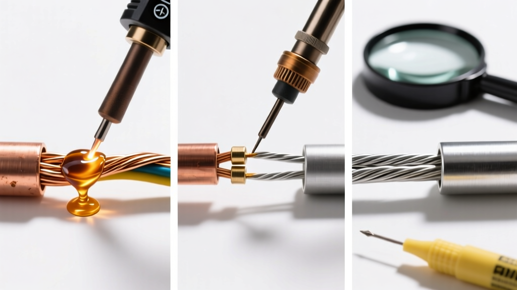
The bond strength in both processes does not come from mechanical interlocking alone, but from the formation of a thin intermetallic compound (IMC) layer at the interface between the filler and the base metal. Managing the thickness and composition of this IMC layer is the hallmark of a professional.
Joining Process Comparison Matrix
| Characteristic | Soldering | Brazing | True Welding (TIG/MIG) |
|---|---|---|---|
| Temperature Threshold | < 840°F (450°C) | > 840°F (450°C) | Base Metal Melting Point |
| Base Metal State | Solid | Solid | Liquid (Fused) |
| Primary Joining Force | Capillary / IMC Adhesion | Capillary / IMC Adhesion | Metallurgical Fusion |
| Typical Joint Clearance | 0.002' - 0.005' | 0.001' - 0.003' | Root Gap / Bevel Dependent |
| Base Metal Annealing Risk | Very Low | Moderate to High | High (HAZ formation) |
Professional Brazing: Capillary Action and Alloy Selection
Brazing is the go-to process for joining dissimilar metals (like copper to steel) or creating high-strength joints in thin-walled tubing where welding would cause burn-through. The secret to a flawless braze lies in joint clearance and flux chemistry.
The Physics of Joint Clearance
Capillary action is inversely proportional to the gap width, but only to a point. According to extensive research by the Copper Development Association, the optimal radial clearance for silver brazing copper-to-copper or copper-to-brass joints at room temperature is between 0.0015' and 0.003'. If the gap is too wide (exceeding 0.005'), capillary force fails, and the filler metal will simply pool at the joint entrance. If the gap is too tight (under 0.001'), the flux cannot be expelled from the joint, leading to flux inclusions that act as stress concentrators and corrosion initiation sites.
Alloy and Flux Pairing for 2026
With silver spot prices remaining volatile in 2026, selecting the right BAg (Silver Brazing) classification is critical for both cost and performance.
- BAg-24 (50% Ag, 15.5% Cu, 16% Zn, 18% Cd-free equivalent): Excellent for tight clearance joints. Melts at 1225°F. Expect to pay roughly $220 per pound for high-quality rods like Harris Safety-Silv 50. Use with a borax-based white flux (AWS FB3-A) active between 1050°F and 1600°F.
- BAg-7 (56% Ag, 22% Cu, 17% Zn, 5% Sn): The premium cadmium-free choice for food-service and HVAC refrigeration lines. Melts at a lower 1145°F, reducing the risk of annealing the base copper. Requires a specialized low-temperature black flux to prevent base metal oxidation at lower heat inputs.
Pro Tip: Never use a reducing (carburizing) oxy-acetylene flame for silver brazing. The excess carbon will contaminate the molten silver alloy, causing a porous, brittle joint. Always tune your torch (such as a Smith AW1A) to a strictly neutral flame before applying heat to the base metal.
Advanced Soldering: Intermetallic Compounds (IMCs) in Electronics
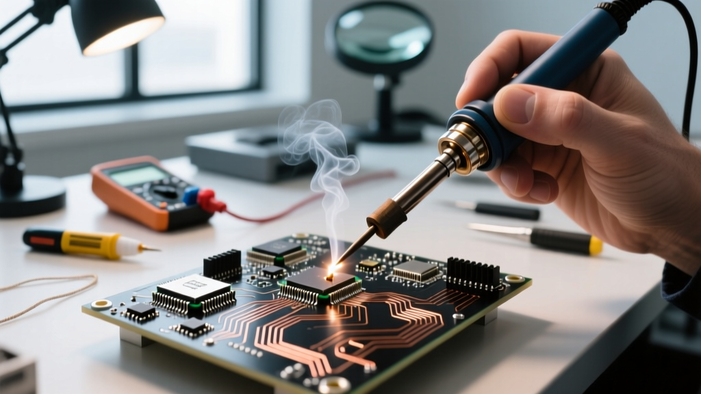
While plumbing soldering relies on bulk mechanical strength, electronic soldering is entirely dependent on the electrical conductivity and thermal fatigue resistance of the Intermetallic Compound (IMC) layer. When tin-based solder contacts a copper pad, they react to form Cu6Sn5 (eta-phase) and eventually Cu3Sn (epsilon-phase).
Managing the IMC Layer
A common misconception is that a thicker IMC layer means a stronger joint. In reality, IMCs are inherently brittle. An ideal IMC layer in a surface mount technology (SMT) or through-hole joint should be between 1 and 3 microns thick. If you apply excessive heat or leave the iron on the pad too long, the IMC layer grows beyond 5 microns, making the joint highly susceptible to micro-cracking under thermal cycling or mechanical shock.
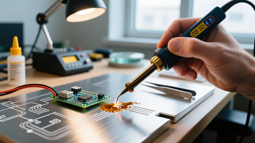
To control this, modern professionals use active-tip soldering stations like the Weller WX2021 or JBC CD-2BE. These stations do not just measure temperature; they measure the thermal mass of the joint and inject wattage dynamically. When soldering a heavy ground plane with SAC305 (Sn96.5/Ag3.0/Cu0.5) lead-free alloy, set the station to 360°C and use a chisel tip with high thermal mass (e.g., JBC C115-114) to achieve reflow in under 2.5 seconds, halting IMC overgrowth.
Flux Chemistry: RMA vs. No-Clean
For high-reliability aerospace or medical electronics governed by IPC Standards (such as IPC-A-610 Class 3), flux selection is paramount. Rosin Mildly Activated (RMA) fluxes provide excellent wetting and leave a hard, protective residue that traps ionic contaminants. However, in high-density 2026 PCB designs with BGA (Ball Grid Array) components, No-Clean fluxes (based on synthetic resins and weak organic acids) are preferred to avoid the risk of electrochemical migration (dendrite growth) under low-voltage, high-impedance circuits.
Joint Design Frameworks for Maximum Shear Strength
Because brazing and soldering rely on adhesion rather than fusion, joint geometry must maximize surface area. The butt joint is the weakest configuration for capillary joining, as it relies solely on the cross-sectional area of the filler metal.
The Lap Joint Rule of Thumb
The lap joint is the gold standard for brazed and soldered assemblies. The professional rule of thumb for calculating lap length is:
Lap Length = 3 × (Thickness of the thinner base metal member)
For example, if you are brazing a 0.050' thick copper tube to a 0.100' thick steel fitting, your minimum lap length should be 0.150'. Extending the lap beyond 3x the thickness yields diminishing returns in shear strength and wastes expensive silver filler alloy, while increasing the difficulty of achieving uniform capillary fill.
Scarf Joints for Tubing
When joining thin-walled tubing where a socket fitting is unavailable, use a scarf joint cut at a 30-degree angle. This triples the surface area compared to a square butt cut and maintains a smooth internal diameter, which is critical for hydraulic or refrigerant lines to prevent turbulent flow and pressure drops.
Troubleshooting Edge Cases and Failure Modes
Even with perfect joint design, field conditions introduce variables that cause failures. Here is how to diagnose and correct the most common issues:
- Flux Inclusions (Brazing): Appears as dark, glassy pockets in the fillet. Cause: Joint clearance too tight, or heating the filler rod directly instead of the base metal. Fix: Heat the base metal until the flux turns clear and liquid, then touch the rod to the joint edge so capillary action draws it in, pushing the flux ahead of the molten front.
- Cold Joints (Soldering): Appears dull, gray, and grainy rather than bright and shiny. Cause: Insufficient heat to form the IMC layer, or movement during the solidification phase. Fix: Re-flow the joint with fresh flux and a clean, tinned iron tip. Never simply 'melt' the old solder without adding fresh flux, as the original flux has likely been exhausted and oxidized.
- Base Metal Erosion (Soldering/Brazing): The base metal appears to dissolve into the filler. Cause: Using a filler with high solubility for the base metal (e.g., high-tin solders on thin copper) at excessive temperatures. Fix: Lower the temperature and switch to a filler with a lower base-metal solubility, such as adding a small percentage of nickel or antimony to the alloy.
Conclusion
Mastering the techniques behind what laymen call 'brazing and soldering welding' requires abandoning the welding mindset entirely. By respecting the 840°F thermal threshold, engineering joint clearances to the thousandth of an inch, and understanding the microscopic IMC layers that dictate joint integrity, you elevate your work from simple assembly to professional metallurgical joining. Whether you are fabricating high-pressure HVAC manifolds or assembling high-frequency RF boards, precision in thermal management and alloy chemistry will always dictate your success.