
The Metallurgical Divide: Understanding the Processes
When a fabricated assembly fails under mechanical or thermal stress, the root cause often traces back to a fundamental misunderstanding of the joining process used. While soldering, welding, and brazing all utilize a filler material to unite base metals, their metallurgical mechanics, thermal thresholds, and failure modes are vastly different. According to the American Welding Society (AWS), misapplying a troubleshooting technique from one discipline to another guarantees catastrophic joint failure. To fix a weak joint, you must first correctly identify the thermal and mechanical boundaries of the process that created it.
| Process | Temperature Threshold | Base Metal State | Primary Filler Examples | Common Failure Modes |
|---|---|---|---|---|
| Soldering | Below 450°C (842°F) | Solid (No melting) | SAC305, Sn63Pb37 | Cold joints, dewetting, flux inclusions |
| Brazing | Above 450°C (842°F) | Solid (No melting) | BCuP-5, BAg-24 | Capillary voiding, thermal shock cracking |
| Welding | Above base metal melting point | Liquid (Fused) | ER70S-6, ER4043 | Porosity, undercut, lack of fusion |
Soldering Troubleshooting: Fixing Low-Temperature Joint Failures
Soldering occurs strictly below 450°C (842°F). The base metal remains solid while the filler metal melts and wets the surface via metallurgical bonding (intermetallic compound formation). In electronics and precision plumbing, the most common defects are cold joints, dewetting, and non-wetting.
Failure Mode: Cold Joints and Intermetallic Disruption
A cold joint in modern lead-free SAC305 (Sn96.5/Ag3.0/Cu0.5) solder typically presents as a dull, grainy, or fractured surface. This occurs when the joint is disturbed during the critical phase-change transition (217°C to 220°C) or when the thermal mass of the pad exceeds the soldering iron's recovery rate. Under IPC-A-610 standards, a disturbed or cold joint is a definitive defect that compromises long-term reliability.
The Fix: Thermal Profiling and Flux Revival
- Do not just add more solder. Adding fresh solder over a cold joint traps oxidized flux and creates a chaotic, brittle intermetallic layer.
- Apply fresh flux: Use a no-clean tacky flux (e.g., Amtech NC-559-V2-TF) to break down the oxidized surface layer and lower the surface tension.
- Reflow with adequate dwell time: Apply a 350°C (662°F) iron tip (using a chisel tip for maximum surface area transfer) for 2 to 3 seconds until the solder flows like liquid glass. Remove the iron and hold the components perfectly still for 4 seconds to allow a uniform intermetallic layer to form.
Brazing Troubleshooting: Capillary Action & Oxidation Nightmares
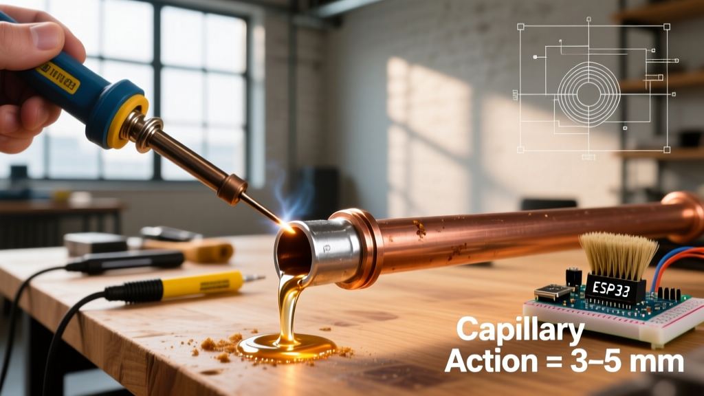
Brazing operates above 450°C (842°F) but strictly below the melting point of the base metals. It relies entirely on capillary action to draw the filler metal into the joint. HVAC, aerospace, and high-pressure plumbing systems frequently suffer from brazing defects when joint clearances are miscalculated or surface preparation is ignored.
Failure Mode: Lack of Capillary Penetration (Voiding)
If you are brazing copper-to-copper using a BCuP-5 (15% silver, phosphorus-bearing) alloy and the filler metal balls up on the surface rather than drawing into the fitting, you are experiencing a capillary failure. This is almost always caused by thermal expansion altering the joint clearance or severe surface oxidation blocking the flow path.
The Fix: Precision Clearances and Chemical Cleaning
Critical Tolerance: Optimal brazing clearance for copper and brass alloys is between 0.002 and 0.005 inches at the brazing temperature, not room temperature. Metals expand when heated; a room-temperature slip-fit will often become too tight at 1,300°F, choking off capillary flow.
Step-by-Step Correction:
- Disassemble and Abrade: Mechanically clean the tube and fitting interior with a stainless-steel wire brush. Do not use sandpaper, which embeds silica into the copper pores and blocks wetting.
- Chemical Fluxing: Even though BCuP alloys are self-fluxing on copper, applying a white borax-based flux (like Harris Stay-Silv) provides a secondary oxygen barrier when dealing with stubborn oxidation or when brazing copper to brass.
- Heat Distribution: Apply the oxy-acetylene torch to the fitting, not the tube. The fitting has more mass and needs to reach the 1,300°F cherry-red state before the filler rod touches the joint edge.
Welding Troubleshooting: High-Heat Fusion Defects
Welding involves melting both the base metal and the filler metal to create a unified weld pool. When MIG (GMAW) or TIG (GTAW) welds fail, the defects are usually structural: porosity, undercut, or lack of fusion. The AWS provides strict visual inspection criteria for these high-heat processes.
Failure Mode: Porosity and Wormholing (MIG/GMAW)
Porosity appears as small cavities or "wormholes" inside or on the surface of the weld bead. When welding mild steel with ER70S-6 wire, porosity is almost exclusively a shielding gas failure. Atmospheric nitrogen and oxygen are contaminating the molten weld pool, becoming trapped as the metal freezes.
The Fix: Gas Flow Dynamics and Surface Prep
- Verify Flow Rate: Check your regulator. For a standard 75% Argon / 25% CO2 (C25) mix, the flow rate must be strictly between 20 and 25 CFH (Cubic Feet per Hour). Anything above 30 CFH creates turbulence that actually pulls air into the shielding envelope.
- Eliminate Drafts: According to OSHA welding safety and operational guidelines, environmental controls are critical. A cross-breeze as low as 5 mph will strip your shielding gas. Use welding screens to block HVAC drafts and shop fans.
- Degrease the Base Metal: ER70S-6 has high deoxidizers (silicon and manganese), but it cannot burn through heavy rust, paint, or mill scale. Grind the joint to bright, shiny metal within 1 inch of the weld zone using a 36-grit flap disc.
Failure Mode: Tungsten Inclusions and Arc Wander (TIG/GTAW)
When TIG welding aluminum (e.g., 6061-T6) with an ER4043 filler rod, a common failure is tungsten contamination. If the tungsten electrode dips into the molten puddle, it alters the arc characteristics and embeds a brittle, high-melting-point inclusion in the aluminum matrix. This creates a localized stress riser that will crack under cyclic loading.
The Fix: Crater Removal and Arc Length Control
Immediately stop welding. Do not attempt to melt the tungsten out of the puddle. You must grind out the contaminated crater using a carbide burr or die grinder until you reach clean, shiny aluminum. Furthermore, re-grind or snap the tungsten electrode to expose a fresh, uncontaminated tip before re-striking the arc. Maintain a strict arc length of 1/16th of an inch (roughly the diameter of the tungsten) to prevent accidental dipping.
Diagnostic Matrix: Identifying Your Joint Failure
| Visual Symptom | Process | Root Cause | Immediate Corrective Action |
|---|---|---|---|
| Dull, grainy, or cracked surface | Soldering | Joint movement during phase change; insufficient heat | Reflow with fresh no-clean flux; increase iron dwell time |
| Filler metal balls up, won't draw in | Brazing | Oxidation; improper thermal expansion clearance | Disassemble, wire brush, apply borax flux, heat the fitting |
| Pinholes or wormholes in bead | Welding (MIG) | Shielding gas turbulence; draft contamination | Reduce gas to 20-25 CFH; block cross-breezes; grind to bare metal |
| Dark, brittle inclusions in puddle | Welding (TIG) | Tungsten electrode dipped into molten pool | Grind out crater; snap/grind tungsten tip; shorten arc length |
Final Thoughts on Metallurgical Integrity
Whether you are reflowing a microscopic 0402 SMD component with SAC305, brazing a 2-inch refrigeration line with BCuP-5, or MIG welding a 1/4-inch steel chassis with ER70S-6, the physics of metal joining remain unforgiving. Troubleshooting requires respecting the thermal thresholds and chemical environments unique to soldering, welding, and brazing. Always prioritize joint preparation, precise gap tolerances, and thermal management over brute-force heat application to ensure structural and electrical integrity.