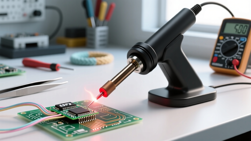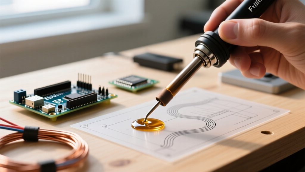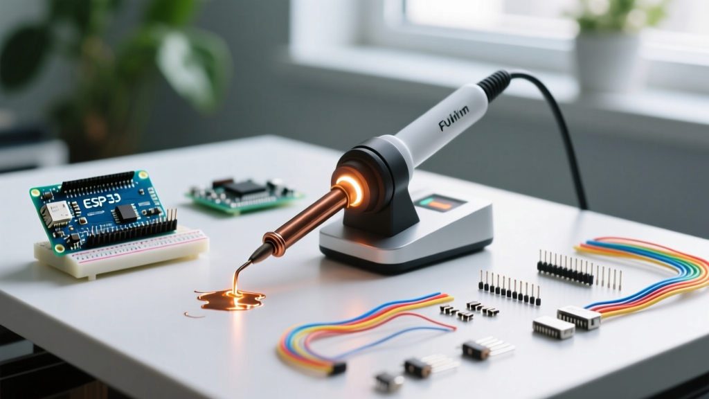

The Science of Soldering Heat: Why 'Hotter' Isn't Always Better
When professionals and hobbyists ask what temperature for soldering iron is ideal, the universal baseline for standard 63/37 tin-lead (Sn/Pb) solder is 320°C (608°F). However, treating this single number as a universal rule is a fast track to lifted pads, oxidized tips, and brittle joints. In 2026, with the dominance of lead-free SAC305 alloys and ultra-dense multi-layer PCBs, dialing in the exact thermal profile is a matter of matching your solder alloy, tip geometry, and component thermal mass.
According to the IPC J-STD-001 requirements for soldered electrical and electronic assemblies, the goal is to achieve proper wetting and intermetallic compound (IMC) formation in the shortest time possible. Overheating accelerates IMC growth, resulting in brittle, glass-like joints that fail under mechanical stress or thermal cycling.
The Master Soldering Temperature Comparison Chart
Use this matrix as your baseline reference. These temperatures assume you are using a high-quality, temperature-controlled station with adequate thermal recovery, not a cheap unregulated mains-powered iron.
| Solder Alloy | Melting Point | Ideal Iron Temp | Target Dwell Time | Primary Use Case |
|---|---|---|---|---|
| 63/37 Sn/Pb (Eutectic) | 183°C (361°F) | 300°C - 330°C | 1.5 - 3 Seconds | Prototyping, hobbyist, vintage repair |
| SAC305 (Lead-Free) | 217°C (423°F) | 340°C - 370°C | 2 - 4 Seconds | Commercial PCB manufacturing, RoHS |
| Sn96.5/Ag3/Cu0.5 | 217°C (423°F) | 350°C - 380°C | 2 - 4 Seconds | High-reliability automotive/aerospace |
| 50/50 Sn/Pb (Solid Wire) | ~212°C (414°F) | 360°C - 410°C | 4 - 8 Seconds | Stained glass, copper foil, plumbing |
Best Soldering Stations for Precision Temperature Control (2026)
Maintaining the correct temperature under load (when the cold copper pad sucks heat away from the tip) requires a station with fast sensor feedback. Here is how the top three stations compare in real-world thermal recovery.
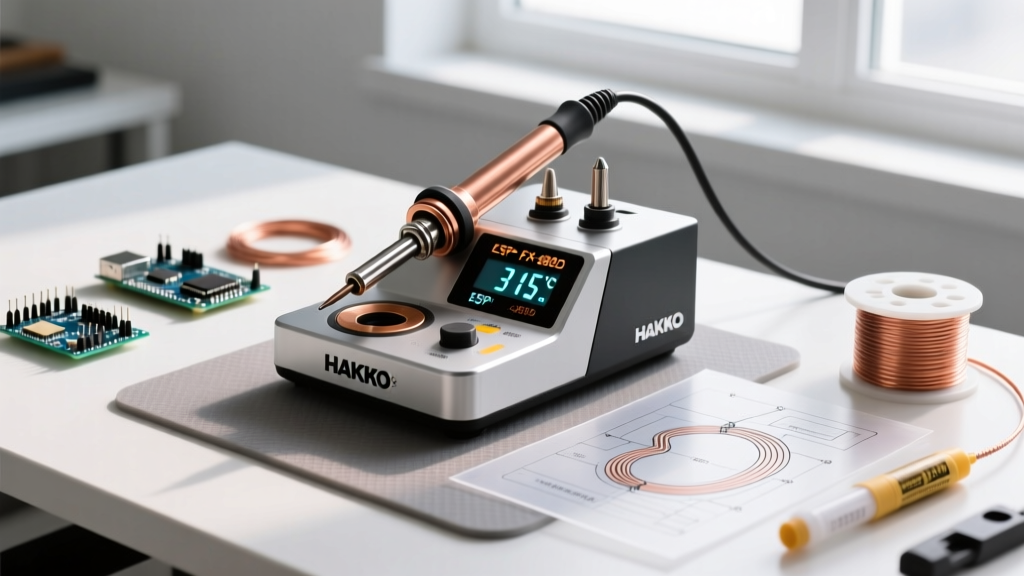
1. Hakko FX-951 (The Professional Standard)
- Price: ~$265 USD
- Wattage: 70W (Composite Tip)
- Thermal Recovery: < 2 seconds
- Expert Take: The FX-951 uses a composite tip where the heating element is embedded inside the tip itself. This eliminates the air gap found in older ceramic heaters, providing near-instantaneous thermal transfer. It is the gold standard for heavy ground-plane soldering.
2. Weller WE1010NA (The Mid-Range Workhorse)
- Price: ~$115 USD
- Wattage: 70W (ET / Micro Tips)
- Thermal Recovery: ~5 seconds
- Expert Take: An excellent entry-level professional station. It features a 10-second sleep mode and password-protected temperature locking, making it ideal for shared maker-spaces or educational labs where users tend to crank the heat unnecessarily.
3. Pine64 Pinecil V2 (The Smart Open-Source Choice)
- Price: ~$26 USD
- Wattage: 65W (via USB-C PD)
- Thermal Recovery: ~3 seconds
- Expert Take: Running on a RISC-V chip and open-source IronOS, the Pinecil V2 offers PID tuning that rivals $300 stations. By pairing it with a 65W+ GaN USB-C laptop charger, you get lab-grade temperature tracking in your pocket.
Scenario-Based Temperature Profiles
The correct answer to 'what temperature for soldering iron' changes drastically based on the thermal mass of the joint you are attacking.
Scenario A: 0402 / 0603 SMD Components (Low Thermal Mass)
Tiny surface-mount components have almost zero thermal mass. If you apply 380°C heat, the component body will absorb the heat instantly, potentially cracking ceramic capacitors or melting plastic IC housings.
- Target Temp: 290°C - 310°C (for Sn/Pb)
- Tip Geometry: Fine hoof or micro-chisel (1.0mm - 1.6mm)
- Technique: Tin one pad, hold the component with tweezers, and drag the iron for exactly 1 second. Rely on flux tackiness rather than prolonged heat.
Scenario B: Multi-Layer PCB with Heavy Ground Planes (High Thermal Mass)
Soldering a capacitor lead into a via that connects to a 4-layer internal ground plane is a common frustration. The ground plane acts as a massive heatsink.
Critical Rule: Never simply crank your station to 450°C to compensate for a ground plane. You will burn the flux and oxidize the pad before the internal layers reach melting temperature.
- Target Temp: 360°C - 380°C (for Lead-Free)
- Tip Geometry: Heavy bevel or wide chisel (3.2mm - 5.0mm)
- Technique: Maximize surface area contact. If the joint still takes longer than 4 seconds to flow, you must introduce a bottom preheater set to 120°C to reduce the delta-T (temperature differential) the iron must overcome.
The Hidden Costs of Incorrect Temperatures
Understanding failure modes is crucial for mastering thermal management. The NASA Electronic Parts and Packaging (NEPP) Program extensively documents how thermal abuse compromises high-reliability electronics.
1. The 'Too Hot' Failure Mode (>400°C for standard alloys)
When an iron is set too high, the rosin or synthetic resin in your flux vaporizes instantly upon contact. This leaves you with raw solder and bare copper, resulting in a dry, grainy, non-wetting joint. Furthermore, tip oxidation accelerates exponentially above 380°C. A $12 Hakko T18 tip that should last six months will pit and dissolve its iron plating in a matter of weeks if left idling at 420°C.
2. The 'Too Cold' Failure Mode (<280°C)
Under-heating leads to incomplete intermetallic compound (IMC) formation. The solder may look shiny initially, but it hasn't chemically bonded to the copper; it has merely 'stuck' to it. These cold joints are highly susceptible to micro-fractures during thermal expansion and contraction. Additionally, attempting to force a cold joint by holding the iron in place for 8+ seconds will eventually delaminate the copper pad from the FR4 fiberglass substrate.
Tip Geometry vs. Temperature: The Surface Area Secret
Many beginners ask what temperature for soldering iron is best, when the real issue is their tip shape. Heat transfer is governed by the equation Q = hA(T), where 'A' is surface area.
A 0.5mm conical (pointed) tip set to 400°C will transfer less actual heat energy into a large wire than a 3.0mm chisel tip set to 330°C. The conical tip only touches the wire at a microscopic point, creating a massive thermal bottleneck. Always choose the widest tip geometry that the physical spacing of your pads allows, and run it at a lower, safer temperature. For comprehensive tip care and geometry selection, the Hakko Soldering 101 guide remains an indispensable resource for avoiding premature tip death.
Expert Calibration and Maintenance Workflow
To ensure your station's digital readout matches the actual tip temperature, follow this workflow:
- Verify with a Thermocouple: Once a quarter, use a K-type thermocouple with a dab of high-temp thermal paste placed directly on the tip to verify the station's internal PID calibration.
- Match Tip to Task: Swap to a high-thermal-mass tip before starting a heavy-duty job rather than increasing the global temperature setting.
- Utilize Sleep Modes: Always use a stand with auto-sleep (dropping the tip to 150°C when idle). This preserves the flux core inside your solder wire and prevents the tip's iron plating from reacting with ambient oxygen.
- Tin Before Storing: Never wipe the tip completely clean before turning off the station. Apply a thick blob of cheap, heavily fluxed 60/40 solder to coat the working surface. This sacrificial layer oxidizes instead of your tip's working face.
Final Verdict
There is no single magic number. For 90% of standard through-hole and SMD electronics work using 63/37 Sn/Pb solder, setting your station to 320°C (608°F) with a 2.4mm chisel tip is the ultimate sweet spot. Transition to 350°C (662°F) only when moving to lead-free SAC alloys or tackling heavy ground planes, and always prioritize tip surface area over raw temperature settings to achieve professional, IPC-compliant joints.