The True Definition: Beyond 'A Tool That Melts Metal'
When a beginner asks what a soldering iron means, they are usually looking for a simple dictionary definition: a handheld tool used to melt solder and join electronic components. However, when an experienced PCB designer or repair technician asks what a soldering iron means for their workbench, the conversation shifts entirely to thermal dynamics, recovery rates, and sensor architecture. In 2026, with the proliferation of high-density surface-mount devices (SMD) and multi-layer boards featuring massive ground planes, understanding the true meaning behind your iron's specifications is the difference between a reliable IPC Class 3 joint and a lifted pad.
This technique guide decodes the engineering realities behind soldering station specifications. We will explore what wattage, thermal mass, and sensor proximity actually mean in practice, and how to translate these concepts into precise muscle memory for modern electronics assembly.
Decoding the Specs: Wattage vs. Thermal Mass
The most common misconception in electronics is that higher wattage automatically means a hotter or better iron. In reality, wattage simply dictates the maximum power draw of the heating element. What truly matters for technique is thermal mass and thermal recovery.
- Wattage: The rate at which the heater can generate heat (measured in Watts). A 70W iron can generate heat faster than a 40W iron.
- Thermal Mass: The physical volume and material density of the tip. A heavy, copper-core chisel tip holds significantly more thermal energy than a thin, hollow conical tip.
- Thermal Recovery: The time it takes for the tip to return to its set temperature after transferring heat to a cold component lead and PCB pad.
Expert Insight: A 40W iron with a massive solid-copper chisel tip will often outperform a 60W iron with a microscopic conical tip when soldering large through-hole connectors to heavy ground planes. The conical tip lacks the thermal mass to prevent the temperature from plummeting upon contact, leading to cold solder joints.
The Sensor Proximity Factor
If you want to know what a premium soldering iron means for SMD rework, look at the sensor placement. Budget irons place the temperature sensor inside the ceramic heating element, separated from the actual tip apex by several millimeters of air and metal. This creates thermal lag. When the tip touches a cold pad, the apex temperature drops, but the sensor doesn't register the drop immediately. By the time the heater kicks in, the joint has already suffered thermal shock.
Premium systems, such as those utilizing JBC C245 cartridges or Weller's active tip technology, integrate the thermocouple directly into the tip, less than 2mm from the apex. This means the station detects heat loss in milliseconds, driving the heater to recover before the solder even begins to solidify.
2026 Station Comparison: What the Specs Mean in Reality
| Model | Wattage | Tip Series | Sensor Location | Recovery Time (350°C) | Est. Price |
|---|---|---|---|---|---|
| Pine64 Pinecil V2 | 65W (PD) | TS100 Compatible | Mid-shaft (Integrated) | ~2.5 seconds | $26 |
| Hakko FX-888D | 70W | T18 | Heater Core (Separated) | ~6.0 seconds | $110 |
| Weller WE1010NA | 70W | ET (Active) | Inside Tip Base | ~3.5 seconds | $115 |
| JBC CD-2BQE | 130W | C245 (Cartridge) | Tip Apex (<2mm) | < 1.0 second | $495 |
Note: Recovery time represents the approximate duration to return to a 350°C setpoint after a 25°C thermal drop induced by a standard 14AWG wire connection.
Technique Application: Translating Specs into Muscle Memory
Understanding what your soldering iron means is useless without applying it to your physical technique. Here is how to adapt your workflow based on thermal dynamics.
The 3-Second Rule for Through-Hole
According to the NASA Workmanship Standards for electronic assembly, prolonged heat application degrades the copper-to-FR4 bond, leading to pad delamination. Your technique should follow a strict timeline:
- Second 1: Apply the tinned tip to both the component lead and the PCB pad simultaneously. This pre-heats the metals.
- Second 2: Feed the solder wire into the joint, not the iron tip. The flux activates between 150°C and 200°C, cleaning the oxides.
- Second 3: The solder flows via capillary action into the barrel. Remove the solder wire, then remove the iron.
If the joint does not flow within 3 seconds, your iron's thermal mass is too low for the joint size, or your tip geometry is incorrect. Do not simply hold the iron there longer; switch to a wider chisel tip to increase surface area contact.
Flux Activation Windows
Flux is the unsung hero of soldering. Modern no-clean and rosin mildly activated (RMA) fluxes require specific thermal windows to volatilize and remove oxidation. If your iron is set to 400°C to 'compensate' for a poor tip, you will instantly burn the flux upon contact, leaving a charred residue that prevents wetting. For standard SAC305 lead-free solder, a tip temperature of 350°C to 360°C is optimal. For eutectic Sn63/Pb37, 320°C is ideal. For deeper insights into lead-free profiles, refer to the IPC Standards overview on thermal profiling.
IPC Standards and Wetting Angles
What does a perfect solder joint mean? The Adafruit Guide to Excellent Soldering and IPC-A-610 guidelines define a reliable joint by its wetting angle and fillet shape. A proper joint exhibits a smooth, concave fillet with a wetting angle of less than 90 degrees. This concave shape proves that the solder alloy metallurgically bonded with the copper, forming an intermetallic compound (IMC) layer.
If your joint looks like a dull, convex blob (a 'ball' sitting on the pad), it means the iron failed to transfer enough heat to the pad itself, resulting in a cold joint where the solder merely glued to the surface flux residue rather than alloying with the metal.
Frequently Asked Questions
What does it mean when my soldering iron tip turns black?
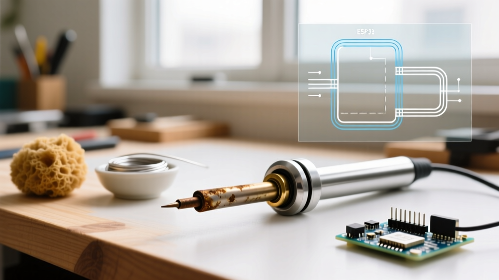
A black tip means oxidation has formed a thermal barrier on the iron plating. This happens when the iron is left on at high temperatures without a protective coat of solder. To prevent this, always 'tin' your tip with a thick blob of solder before turning the station off. Never use a wet sponge to clean the tip, as the rapid thermal shock causes micro-fractures in the iron plating; use brass wire wool instead.
What does a 'curie temperature' soldering iron mean?
Curie-point irons (like older Metcal systems) use a magnetic alloy in the tip. When the tip reaches its specific Curie temperature, it loses its magnetic properties, stopping the induction heating instantly. This means the iron physically cannot exceed its designed temperature, offering perfect thermal regulation without digital sensors, though modern digital stations have largely matched this performance at a lower cost.
Why does my 60W iron struggle with large ground planes?
Large ground planes act as massive heat sinks, pulling thermal energy away from the tip faster than a standard 60W heater can replenish it. To solve this, use a station with high thermal recovery (like a JBC or Weller active-tip system) and pair it with a heavy, wide chisel tip (e.g., 3.2mm or larger) to maximize the physical contact area and thermal transfer rate.