
The Enduring Relevance of the WLC100 Soldering Iron in 2026
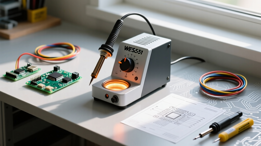
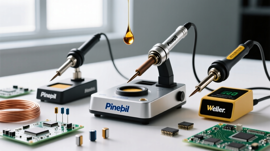
Even in 2026, amidst the proliferation of USB-C PD smart irons and high-wattage digital stations, the analog Weller WLC100 soldering iron remains a staple on the workbenches of dedicated electronics repair technicians and hobbyists. Producing a steady 40 watts of power via a ceramic heating element, this station is celebrated for its rugged simplicity and zero-crossing power control. However, its lack of digital temperature readouts and relatively low wattage compared to modern 65W+ stations means that mastering the WLC100 soldering iron requires a deep understanding of thermal dynamics, tip geometry, and manual calibration.
This technique guide bypasses basic soldering primers and dives directly into the advanced operational nuances of the WLC100. We will cover precise dial-to-temperature mapping, Weller ST-series tip selection matrices, and step-by-step methodologies for both fine-pitch surface mount and high-mass through-hole soldering.
Understanding the WLC100 Thermal Profile and Recovery Limits
The primary limitation of the WLC100 soldering iron is its thermal recovery time. When a 40W iron contacts a copper ground plane, the tip temperature drops rapidly. While a 80W digital station might recover in 2 seconds, the WLC100's ceramic heater requires between 8 to 15 seconds to stabilize back to its setpoint. Understanding this thermal lag is the difference between a pristine, shiny fillet and a dull, disturbed cold joint.
To compensate for this, technicians must employ a 'pre-heat and dwell' strategy rather than a 'touch and drag' approach. Furthermore, the WLC100 uses a TRIAC-based dial control. It does not measure the tip temperature directly; instead, it regulates the duty cycle of the AC power sent to the heater. Therefore, the dial setting must be adjusted based on the thermal mass of the component you are soldering, not just the melting point of the solder alloy.
Dial Calibration: Mapping the 1-10 Power Scale
Because the WLC100 lacks an LCD screen, users must memorize the correlation between the dial position (1 through 10) and the approximate tip temperature. The following calibration matrix assumes a standard 63/37 SnPb rosin-core solder and a clean ST-series tip in a standard 72°F (22°C) ambient environment.
| Dial Setting | Approx. Temp (°F / °C) | Ideal Application & Alloy Match |
|---|---|---|
| 1 - 2 | 200°F - 350°F (93°C - 176°C) | Heat shrink tubing manipulation; low-temp paste reflow. |
| 3 - 4 | 350°F - 500°F (176°C - 260°C) | Delicate 0402 SMD components; Sn42/Bi57 low-temp alloy. |
| 5 - 6 | 500°F - 650°F (260°C - 343°C) | Standard 0805/0603 SMD, DIP ICs; 63/37 SnPb (Kester 245). |
| 7 - 8 | 650°F - 750°F (343°C - 398°C) | Lead-free SAC305 alloys; multi-layer PCB through-hole vias. |
| 9 - 10 | 750°F - 900°F (398°C - 482°C) | Heavy gauge wire (12-14 AWG), large solder lugs. High oxidation risk. |
Pro-Tip for Lead-Free Transition: If you are transitioning from leaded to lead-free SAC305 solder on the WLC100, you must increase the dial setting by at least 2 full increments and switch to a higher thermal mass tip (like the ST7) to compensate for the 40°C higher melting point and poor wetting characteristics of lead-free alloys.
Weller ST Series Tip Selection Matrix
The WLC100 utilizes the Weller ST series screw-on tips. These tips feature an iron-plated copper core, which provides excellent thermal conductivity but requires careful maintenance to prevent the iron plating from dissolving into the molten solder. Selecting the wrong tip geometry will bottleneck the 40W heater's efficiency.
- ST1 (Conical): Generally avoided for PCB work. The point contact area is too small to transfer heat efficiently to a copper pad, leading to prolonged dwell times and oxidized pads.
- ST4 (Screwdriver): A versatile general-purpose tip. The flat blade allows for good contact on standard through-hole resistors and axial diodes.
- ST6 (1/16" Chisel): The undisputed workhorse for the WLC100. The angled chisel edge provides optimal surface area for 0805 SMD pads and standard 0.1" pitch through-hole headers.
- ST7 (3/32" Heavy Chisel): Required for high-mass connections. The thicker shaft acts as a thermal reservoir, delaying the temperature drop when soldering ground planes or thick wires.
- ST8 (Mini Wave): Specifically designed for drag-soldering fine-pitch SOIC and TQFP surface mount ICs. The concave well holds molten solder via surface tension.
Technique 1: Drag Soldering Fine-Pitch ICs with the ST8 Tip
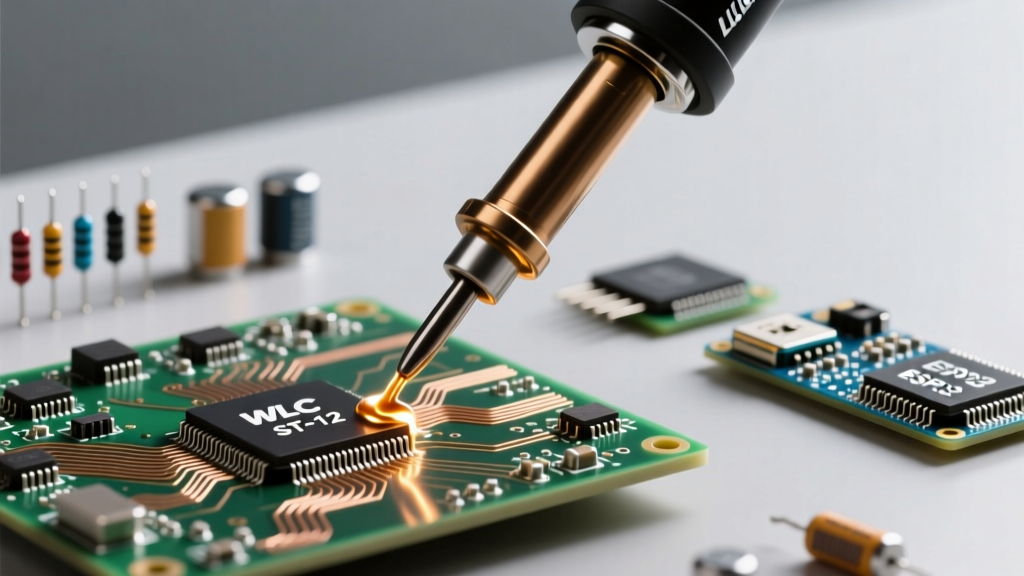
Drag soldering a 0.5mm pitch TQFP microcontroller with a 40W iron requires meticulous flux management and precise dial control. The WLC100 soldering iron excels here because its analog dial allows for smooth, continuous thermal adjustments without navigating digital menus.
- Preparation: Set the WLC100 dial to 5 (approx. 600°F). Tin the ST8 Mini Wave tip with a generous amount of fresh 63/37 solder. Wipe the tip on a dry brass sponge to leave a shiny, oxidized-free surface.
- Flux Application: Apply a high-tack no-clean flux (such as Amtech NC-559-V2-TF) across all IC pads. Do not skimp on flux; it is the primary driver of surface tension during drag soldering.
- Alignment: Tack down two diagonal corner pins using the ST6 chisel tip to lock the IC in place.
- The Drag: Switch to the ST8 tip. Load the tip's concave well with solder. Place the tip at one end of the pin row at a 45-degree angle. Slowly drag the iron across the pins over a 3-second duration. The flux will boil, and the surface tension will pull the exact right amount of solder into each pad.
- Inspection: Inspect under a 10x loupe. If bridges form, clean the ST8 tip completely, apply more liquid flux, and drag across the bridge. The flux will pull the excess solder up into the tip's well.
Technique 2: High-Mass Through-Hole Soldering
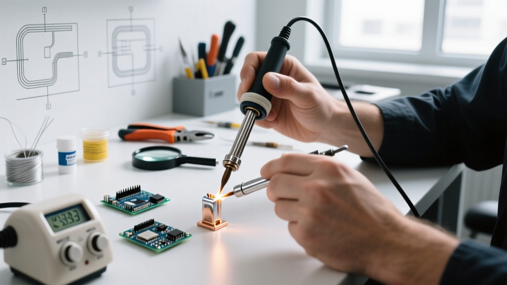
Soldering a 14 AWG wire to a heavy copper lug is where the WLC100 soldering iron is most prone to failure if used incorrectly. The massive copper acts as a heatsink, rapidly draining the 40W element's thermal reserves. As noted in comprehensive guides like SparkFun's Through-Hole Soldering Tutorial, the key is heating the workpiece, not melting the solder directly on the iron.
- Install the ST7 (Heavy Chisel) tip and set the dial to 8 (approx. 720°F).
- Mechanically secure the wire to the lug. A loose mechanical connection will result in a fractured joint once the solder cools.
- Press the flat face of the ST7 tip firmly against the junction where the wire meets the lug. Hold for 3 to 4 seconds to allow the copper to absorb the heat.
- Feed Kester 245 (0.031" diameter) solder into the opposite side of the joint, away from the iron tip. When the copper reaches 361°F, the solder will instantly wick into the stranded wire via capillary action.
- Remove the solder wire first, then remove the iron. Hold the assembly completely still for 5 seconds until the solder transitions from a liquid sheen to a solid, dull matte finish.
Critical Maintenance: Avoiding Thermal Shock and Tip Degradation
The most common cause of premature ST-tip failure on the WLC100 is the use of a wet cellulose sponge. When a 650°F tip touches a damp sponge, the temperature plummets by over 150°F in a fraction of a second. This extreme thermal shock causes microscopic fractures in the iron plating, allowing the molten solder to eat through to the copper core, destroying the tip.
Furthermore, the 40W heater struggles to recover from this massive thermal drop, encouraging users to leave the iron on the joint longer, which burns the flux and creates dry, granular joints. According to the stringent workmanship requirements outlined in NASA-STD-8739.3, proper wetting and thermal management are critical for joint reliability. To maintain your WLC100:
- Discard the damp sponge. Use a dry brass wire sponge (Weller WDC1) to clean the tip between joints.
- Never leave the WLC100 idle at setting 8 or higher. If you are stepping away for more than 2 minutes, turn the dial down to 2. Prolonged high-heat idling accelerates iron plating oxidation.
- Always store the tip with a thick coating of fresh solder to act as a sacrificial oxidation barrier.
FAQ: WLC100 Troubleshooting
Why is my solder balling up and refusing to wet the pad?
This is a classic symptom of a cold pad, often caused by using the ST1 conical tip or a wet sponge. The pad has not reached the solder's liquidus temperature. Switch to an ST6 chisel tip, increase the dial by one increment, and apply additional liquid flux to break down surface oxides.
Can I use the WLC100 for plumbing or stained glass?
No. The WLC100 soldering iron is strictly designed for electronics and light electrical wiring. Plumbing and stained glass require 100W to 250W irons (like the Weller 100PG) to overcome the massive thermal mass of copper pipes and zinc came. The WLC100's 40W element will fail to maintain temperature, resulting in dangerous, structurally unsound plumbing joints.
How does the WLC100 compare to modern digital stations for daily repair work?
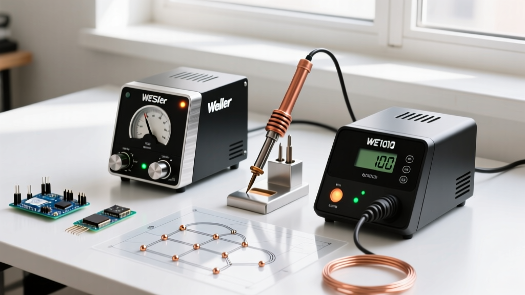
While digital stations like the Weller WE1010NA offer superior thermal recovery and precise readouts, the WLC100 remains highly relevant for technicians who prefer analog tactile feedback and require a station that is immune to ESD events or power surges that can fry digital microcontrollers. When paired with the correct ST tip and proper thermal management techniques, the WLC100 produces joints that easily meet IPC J-STD-001 Class 2 and Class 3 acceptance criteria.