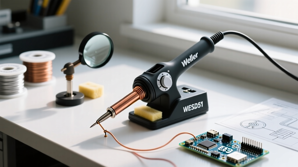

The Enduring Legacy of the Weller WESD51 in 2026
Even in 2026, the Weller soldering iron WESD51 remains a legendary workhorse on professional electronics benches and in prototyping labs. While the WE1010 series has largely taken over retail shelves as its modern successor, the WESD51’s rugged 70-watt digital control loop, heavy-duty transformer, and repairable architecture keep it in active daily use. However, decades of thermal cycling, mechanical stress, and environmental exposure eventually take a toll on any soldering station.
Unlike modern sealed units that are discarded when they fail, the WESD51 is highly serviceable. Whether you are dealing with a flashing 'SENSOR' error, a runaway heater melting your ET-series tips, or simple calibration drift, this guide provides the exact diagnostic steps, multimeter pinouts, and component-level repair data needed to restore your station to factory specifications.
Diagnostic Triage: Isolating the Fault Domain
When your WESD51 fails to maintain temperature or refuses to heat entirely, the fault will always reside in one of three domains: the consumable tip, the WPB70 handpiece, or the main station PCB. Jumping straight to board-level repair without isolating the handpiece is a common mistake that wastes time and money.
Step 1: Inspect the Tip and Thermal Coupling
The ET-series tips rely on a tight mechanical fit between the tip's internal bore and the ceramic heating element/sensor shaft. If the tip is oxidized internally or pitted, thermal transfer drops drastically. The station's PID controller will overcompensate, leading to overshooting temperatures and premature element burnout.
- Visual Check: Remove the tip and inspect the inner bore. If you see heavy blue/black oxidation, the tip is compromised.
- The Fix: Replace the tip. In 2026, genuine Weller ET tips cost between $9 and $14 from authorized industrial distributors. Avoid counterfeit tips, which often feature poorly plated iron cladding that flakes off and shorts the sensor.
Step 2: Multimeter Testing the WPB70 Handpiece
If a new tip does not resolve the issue, you must test the WPB70 handpiece. The heating element and thermocouple sensor are co-wound in a single ceramic assembly. You will need a digital multimeter set to the Ohms (Ω) range.
Disconnect the handpiece from the station and probe the proprietary locking connector pins:
| Test Points | Expected Resistance | Component Tested | Failure Mode Indication |
|---|---|---|---|
| Pin 1 to Pin 3 | 9.0Ω - 15.0Ω | Heating Element | Open (Infinite) = Broken heater wire |
| Pin 3 to Pin 4 | 1.5Ω - 2.5Ω | Thermocouple Sensor | Open (Infinite) = Sensor degradation |
| Pin 2 to Shield/Collar | < 1.0Ω | ESD Ground Path | High resistance = Ground failure |
Note: Pin 2 is tied to the metal collar at the base of the handpiece. According to the ESD Association, maintaining a continuous ground path of less than 1 ohm from the tip collar to the station's earth ground is critical for protecting sensitive MOSFETs and microcontrollers from electrostatic discharge during soldering.
Decoding WESD51 Digital Error Codes
The WESD51's digital display provides specific alphanumeric codes when the internal microcontroller detects an anomaly in the feedback loop. Understanding these codes prevents unnecessary part replacements.
'SENSOR' Error
This indicates the station cannot read the thermocouple. The microcontroller is seeing an open or short circuit across Pins 3 and 4. If the handpiece tests fine on the bench, the fault is likely in the flexible silicone cord. Repeated bending near the strain relief often breaks the ultra-fine sensor wire inside. Replacement WPB70 handpieces run about $85 to $95 in 2026; replacing the cord separately requires specialized high-flex wire and is rarely cost-effective.
'HEATER' Error
This triggers when the control board detects an open or short across Pins 1 and 3. A short circuit here is rare unless the internal ceramic core has shattered. An open circuit means the nichrome heater wire has snapped, usually due to prolonged operation at maximum temperature (450°C+) which accelerates metal fatigue.
'FAIL' Error
A catastrophic internal fault. This typically points to a failed Analog-to-Digital Converter (ADC) on the main PCB or a corrupted EEPROM. At this stage, board replacement or upgrading to a modern WE1010 is the recommended path.
Component-Level PCB Troubleshooting
For technicians comfortable with schematic tracing and soldering, the WESD51 main board is remarkably straightforward. Here are the most common component-level failures observed in stations manufactured between 2005 and 2015.
The 'Runaway Heater' (Shorted Triac)
Symptom: The station powers on, but the tip turns cherry red and melts the solder plating off the tip. The display may read correctly, but the temperature climbs uncontrollably past 450°C.
Root Cause: The main switching Triac (often a BTA12-600B or equivalent) on the PCB has failed in a 'shorted closed' state. The microcontroller is no longer able to pulse the AC waveform to the transformer's secondary side.
The Fix: Desolder the faulty Triac. Clean the pads with isopropyl alcohol and flux. Solder in a new BTA12-600B Triac (cost: <$1.50). Ensure you apply a thin layer of thermal paste between the Triac's metal tab and the aluminum heat sink before tightening the mounting screw.
Flickering Display and Power Supply Capacitors
Symptom: The digital LED display dims, flickers, or resets randomly when the heater engages.
Root Cause: The 5V DC logic rail is sagging under load. This is almost always caused by dried-out electrolytic capacitors on the low-voltage power supply side of the PCB. After 10+ years of thermal exposure inside the metal chassis, the electrolyte boils off.
The Fix: Locate the 1000µF and 470µF electrolytic capacitors on the DC output side of the bridge rectifier. Desolder and replace them with high-quality, low-ESR (Equivalent Series Resistance) capacitors rated for 105°C. As noted by Weller Tools documentation, maintaining stable logic voltage is essential for the PID algorithm to calculate thermal recovery accurately.
Preventative Maintenance Matrix
Adhering to a strict maintenance schedule extends the life of your WESD51 and ensures compliance with IPC J-STD-001 requirements for soldering processes.
| Frequency | Maintenance Task | Procedure & Tools | Expected Cost / Time |
|---|---|---|---|
| Daily | Tip Tinning & Cleaning | Use brass wool (never wet sponges, which cause thermal shock and micro-cracking). Apply fresh 63/37 rosin-core solder before powering off. | $0 / 2 mins |
| Monthly | Element Shaft Dressing | Remove tip. Gently rub the ceramic sensor shaft with a soft brass brush to remove carbon buildup. Do NOT use sandpaper. | $5 (brush) / 5 mins |
| Bi-Annually | Ground Path Verification | Measure resistance from the tip collar to the station's AC earth ground pin. Must be < 1.0Ω. | $0 / 3 mins |
| Annually | Calibration Offset Check | Use a K-type thermocouple tip meter. Compare actual tip temp to digital display. Adjust via front-panel offset if delta is > 5°C. | $120 (meter) / 10 mins |
Mastering Digital Calibration
Unlike the analog WES51, which requires opening the chassis to adjust a physical trimmer potentiometer, the WESD51 features a digital offset calibration menu. This is a massive advantage for precision work.
- Power on the station and allow it to stabilize at 350°C for at least 3 minutes.
- Measure the actual tip temperature using a high-quality tip thermocouple meter (e.g., Hakko FG-100 or Weller WSD-TC).
- Press and hold both the UP and DOWN front-panel buttons simultaneously for 3 seconds.
- The display will flash, entering the offset mode. Use the UP/DOWN buttons to add or subtract the temperature delta until the display matches your external meter.
- Press and hold both buttons again to save the offset to the EEPROM.
Expert Warning: Never attempt to calibrate the WESD51 using a standard infrared thermometer. IR guns measure surface emissivity, which varies wildly based on the oxidation level of the tip's iron cladding. Always use direct-contact thermocouple sensors designed specifically for soldering tips to ensure accurate thermal profiling.
Final Thoughts on Legacy Station Repair
The Weller soldering iron WESD51 represents an era of industrial design where repairability was a feature, not an afterthought. By understanding the specific resistance values of the WPB70 handpiece, recognizing the failure modes of the Triac and electrolytic capacitors, and adhering to strict IPC-compliant tip maintenance, you can keep this 70-watt digital powerhouse running flawlessly for years to come. Whether you are repairing vintage audio equipment or assembling modern SMD prototypes, a well-maintained WESD51 remains a formidable tool in 2026.