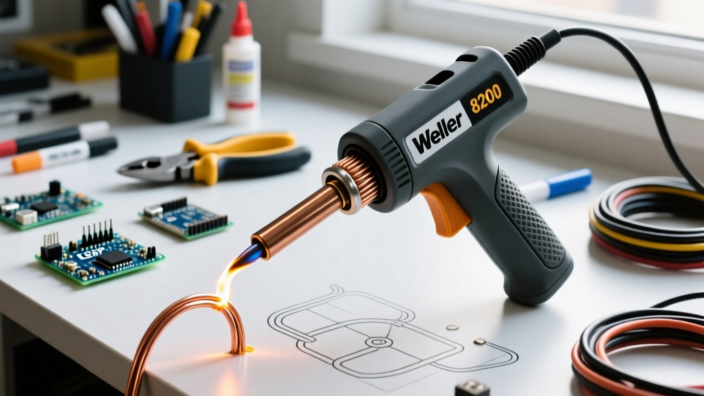

The Anatomy of the Weller 8200: Why It Still Dominates in 2026
While ceramic heating element stations like the WES51 or WE1010NA dominate precision PCB work, the Weller 8200 soldering gun (often sold in kits as the D8200B12) remains an undisputed workhorse for high-thermal-mass applications. Retailing between $55 and $65 in 2026, this 120-watt, 120V AC transformer-based tool delivers instant, massive current to the tip. Unlike resistance-heated ceramic irons that rely on thermal conduction from a core, the 8200 utilizes a step-down transformer. The secondary winding outputs roughly 0.5V to 1.0V at over 150 Amps, turning the copper tip itself into the resistive heating element.
This architecture provides unmatched thermal recovery for heavy-gauge automotive wiring, stained glass foiling, and thick brass connectors. However, it also introduces unique failure modes that novice users frequently encounter. Mastering this tool requires strict adherence to duty cycle management, terminal torque specifications, and flux chemistry.
Critical Failure Modes: Managing the Transformer Duty Cycle
The most common cause of death for the Weller 8200 is transformer burnout resulting from continuous trigger depression. The internal step-down transformer lacks active cooling and relies entirely on passive thermal mass to absorb heat spikes.
Expert Warning: Never hold the trigger continuously for more than 60 seconds. Prolonged activation pushes the transformer core past 150°C. At this threshold, the enamel insulation on the primary windings begins to degrade, leading to inter-winding shorts and catastrophic failure.
The Pulse-Heating Technique
To safely solder large thermal masses without overheating the gun's phenolic (Bakelite) housing, adopt a pulse-heating rhythm:
- Seconds 0–15: Squeeze the trigger fully (120W mode) to bring the tip to operating temperature (approx. 350°C–400°C).
- Seconds 15–20: Release the trigger slightly to drop into the holding heat mode (if your specific 8200 variant supports dual-heat) or release entirely to allow a 5-second cool-down.
- Seconds 20–30: Re-engage to apply heat to the joint, feed solder, and release immediately upon wetting.
Tip Metallurgy and Terminal Torque Specifications
The Weller 8200 uses the CT6 series tips. These tips feature a high-conductivity copper core plated with a thin layer of iron on the working end to resist solder erosion. However, the bare copper at the base—where it interfaces with the secondary bus bar—is highly susceptible to oxidation and galvanic corrosion.
The Thermal Expansion Problem
Every time you pull the trigger, the copper tip expands rapidly due to intense localized heating. When it cools, it contracts. Over 10 to 15 heat cycles, this micro-movement causes the slotted brass terminal screws to back out. A loose screw increases electrical contact resistance, creating a localized hot spot at the terminal that will melt the gun's phenolic housing and permanently ruin the secondary bus bar threads.
Actionable Maintenance: After every 10 hours of use, allow the gun to cool completely and re-torque the terminal screws. Do not exceed 2.5 to 3.0 in-lbs
CT6 Tip Selection Matrix for Heavy-Duty Applications
Choosing the correct tip geometry is critical for maximizing thermal transfer. Below is the definitive guide to matching CT6 tips with specific high-mass tasks.
| Tip Model | Geometry | Thermal Mass | Best Application |
|---|---|---|---|
| CT6F7 | 1/8" Chisel | High | 10-14 AWG automotive wire, heavy ring terminals |
| CT6D | 1/8" Screwdriver | Medium-High | Stained glass copper foiling, large coaxial shields |
| CT6C7 | 3/32" Conical | Medium | 16-18 AWG wire, medium spade connectors |
| CT6B | 1/16" Conical | Low | Not recommended for 8200 (use ceramic station instead) |
Flux Chemistry: Protecting the Iron Plating
When using the Weller 8200 soldering gun for plumbing, automotive, or industrial applications, technicians often reach for acid-core solder or zinc chloride liquid flux. While highly effective for stripping oxides from brass and galvanized steel, acid flux is devastating to the iron plating on CT6 tips.
According to the requirements outlined in the IPC J-STD-001 standard for soldered electrical and electronic assemblies, rosin-based (R, RMA, or RA) or no-clean fluxes are mandated for electrical connections to prevent long-term dendritic growth and corrosion. If you must use acid flux for a mechanical ground strap or non-electrical bracket, you must neutralize and clean the tip immediately afterward using a brass wire sponge and an isopropyl alcohol wipe. Failure to do so will result in deep pitting of the iron plating within a single work session, exposing the copper core to rapid dissolution by the molten tin.
Step-by-Step: Soldering 10 AWG Automotive Wire
Soldering 10 AWG wire to a heavy brass terminal block requires precise heat management to ensure the solder wicks into the strands without burning the wire insulation. We align our workmanship criteria with the stringent wetting and fillet requirements found in the NASA-STD-8739.3 Workmanship Manual, which dictates that a proper joint must exhibit a smooth, continuous concave fillet with visible wire contours.
- Preparation: Strip exactly 3/8" of insulation from the 10 AWG wire. Twist the strands tightly to prevent fraying.
- Pre-Tinning: Apply a small amount of 63/37 leaded eutectic solder (or SAC305 if lead-free compliance is required in 2026) to the bare wire using a chisel tip (CT6F7). The pre-tinning acts as a thermal bridge.
- Terminal Heating: Place the flat face of the 1/8" chisel tip directly against the brass terminal block. Squeeze the trigger for 4–6 seconds to saturate the brass with heat.
- Joint Mating: While maintaining trigger pressure, press the pre-tinned wire into the terminal cup or against the lug.
- Feed Solder: Apply solder to the joint, not the tip. The thermal mass of the brass and wire should melt the solder instantly. Feed until the fillet forms a smooth concave shape.
- Cool Down: Release the trigger. Hold the wire perfectly still for 3 seconds until the solder transitions from liquid to solid to prevent a cold, crystalline joint.
Troubleshooting Common Weller 8200 Faults
The Gun Hums Loudly but Fails to Heat
Diagnosis: High contact resistance at the tip terminals. The transformer is pushing current, but the loose screws are bottlenecking the circuit.
Fix: Unplug the gun. Remove the tip, clean the copper base and brass bus bar with a fiberglass scratch pen, and re-install with fresh screws if the originals are oxidized. Torque to 3 in-lbs.
The Tip Heats Up Instantly and Glows Red
Diagnosis: Shorted secondary winding. The internal enamel insulation on the transformer's secondary coil has melted, causing the windings to bypass and deliver raw line voltage (or dangerously high step-down voltage) to the tip.
Fix: The tool is unsafe and cannot be repaired economically. The transformer core must be replaced, which costs nearly as much as a new D8200B12 kit. Recycle the unit and purchase a replacement.
Solder Balls Up and Refuses to Wet the Tip
Diagnosis: Severe oxidation or iron pitting. The tip has been run dry (without a protective coating of solder) during cooling cycles.
Fix: While the tip is warm, aggressively scrub it in a damp cellulose sponge, then immediately flood it with a heavy coat of 63/37 rosin-core solder to seal the iron plating from atmospheric oxygen.