
The Illusion of the Dial: Why Set-and-Forget Fails
Every electronics engineer and hobbyist has experienced the frustration of a stubborn ground plane joint. You set your station to 350°C, touch the pad, and the solder refuses to flow, forming a dull, grainy cold joint. The root cause is rarely the nominal temperature setting; rather, it is a failure in soldering iron temperature control and thermal recovery. In modern PCB rework, the displayed temperature on your station's LCD is merely a promise. The actual surface temperature of the tip at the moment of contact dictates the metallurgical success of the joint. As we navigate the component densities of 2026, where 0201 passives and high-layer-count boards with massive thermal vias are standard, understanding the deep physics and algorithmic control of your soldering equipment is no longer optional—it is mandatory for compliance with IPC J-STD-001 standards.
The Anatomy of Thermal Feedback Loops
To master temperature control, we must first dissect how modern stations measure heat. Legacy irons utilized a simple bimetallic strip or a separated thermocouple wired near the heating element. This introduced severe thermal lag. Today, the industry relies on integrated cartridge tips.
Thermocouple vs. PTC Thermistor Architectures
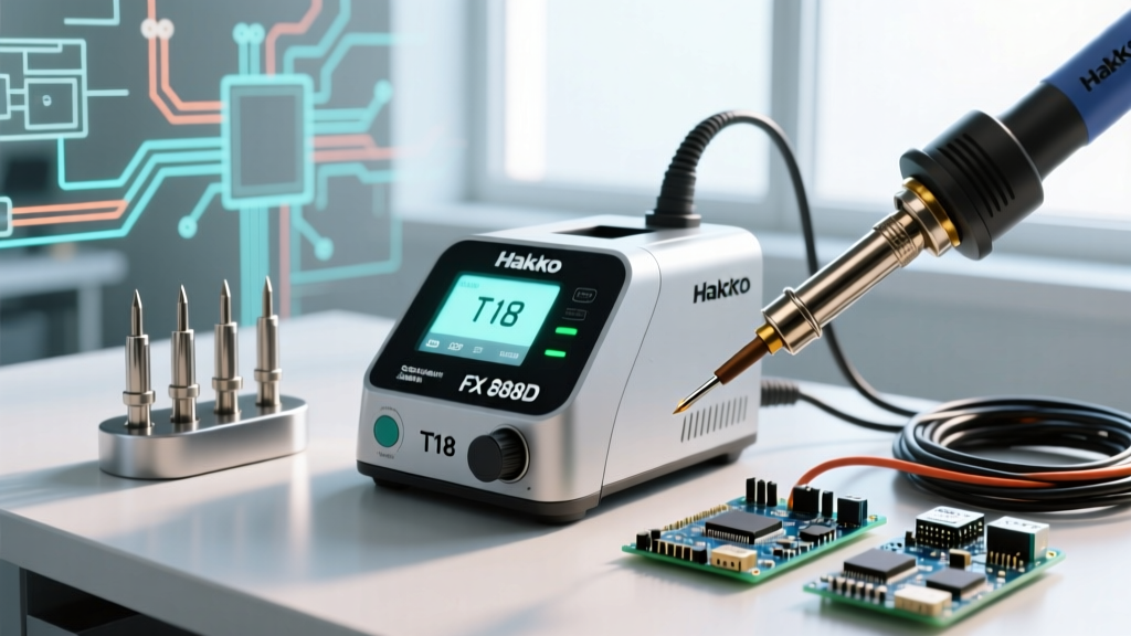
- Hakko T12/T15 Architecture: Employs a K-type thermocouple embedded directly in the tip's copper core, wired in series with the 24V ceramic heater. This provides rapid feedback, but the station must rapidly switch the heater off to read the thermocouple's microvolt signal, creating micro-interruptions in heat delivery.
- Weller RT Series Architecture: Utilizes a unique Positive Temperature Coefficient (PTC) thick-film heater that acts as both the heating element and the temperature sensor. As the tip reaches the Curie temperature of the PTC material, resistance spikes, naturally limiting current. This analog self-regulation is supplemented by digital PID loops in stations like the Weller WE1010NA.
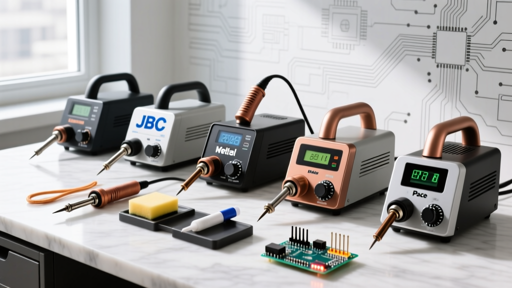
- JBC Cartridge System: JBC stations (like the CD-2BQE) use a proprietary 3-pin connector separating the thermocouple, heater, and ground. This allows the station to read the temperature continuously while delivering up to 130W of power, resulting in near-zero thermal lag.
Control Algorithms: Bang-Bang vs. PID vs. Fuzzy Logic
The method by which the station's microcontroller interprets sensor data and modulates power defines the quality of your soldering iron temperature control. According to foundational PID control theory, a system must manage proportional, integral, and derivative errors to maintain stability.
| Control Type | Mechanism | Overshoot Risk | Thermal Recovery | Common Implementations |
|---|---|---|---|---|
| Bang-Bang (Hysteresis) | Heater is 100% ON below setpoint, 100% OFF above. | High (±15°C) | Poor | Cheap USB irons, legacy analog stations |
| Standard PID | Modulates PWM duty cycle based on P, I, and D error calculations. | Low (±2°C) | Excellent | Hakko FX-951, Weller WE1010NA |
| Fuzzy Logic / Adaptive | AI-driven algorithms that predict thermal drain based on joint mass. | Minimal | Instantaneous | JBC EXCLUSIVE series, high-end Metcal |
In 2026, the proliferation of RISC-V microcontrollers in portable irons like the Pinecil V2 has brought advanced PID tuning to the $26 price point. By leveraging USB-C PD3.1 (up to 240W negotiation), these portable units can execute complex derivative calculations to anticipate temperature drops before the thermocouple even registers them, drastically reducing steady-state error when dragging through thick solder paste.
The Ground Plane Dilemma: Managing Thermal Mass
When you touch a 10-layer PCB with a 2mm thermal via array, the board acts as a massive heat sink. A standard 60W iron will experience an immediate surface temperature drop from 350°C to under 220°C. If you are using SAC305 lead-free solder (melting point 217°C), the joint instantly falls below the liquidus phase, resulting in a disturbed or cold joint.
Pro-Tip for High-Mass Joints: Never compensate for a ground plane by simply turning the dial to 400°C. This will oxidize the tip and degrade the flux before the core of the joint reaches reflow temperature. Instead, increase the thermal mass of your tip. Switching from a standard conical (B-type) to a heavy bevel (C-type) or a wide chisel (D-type) increases the contact surface area and the localized heat reservoir, allowing the PID loop to recover the temperature 40% faster without overshooting.
Step-by-Step Calibration Protocol (Hakko FG-100B Method)
Over time, the internal resistance of the heating element and the tip seating degrades, causing the displayed temperature to drift from the actual surface temperature. Professional labs require bi-annual calibration. Here is the exact procedure using a Hakko FG-100B tip thermometer (approx. $165).
- Preparation: Install a fresh, tinned chisel tip on your station. Set the station to 350°C and allow it to stabilize for 5 minutes.
- Sensor Prep: Apply a small bead of high-temperature thermal transfer paste (provided with the FG-100B) to the K-type thermocouple sensor pad on the tester.
- Contact: Press the iron tip directly onto the sensor pad at a 45-degree angle. Apply exactly 200g of downward pressure (the tester has a built-in spring gauge to verify this).
- Stabilization: Hold the connection until the LCD reading stabilizes for 3 consecutive seconds. Record this value.
- Offset Calculation: If the station reads 350°C but the tester reads 338°C, you have a -12°C offset. Access your station's calibration menu (usually by holding the UP/DOWN arrows simultaneously) and input the +12°C correction factor.
- Verification: Remove the iron, let the tip re-tin, and repeat the process to verify the new offset holds within a ±2°C tolerance.
Hidden Failure Modes: When Temperature Control Lies
Even the most advanced PID algorithm cannot compensate for physical barriers to heat transfer. If your station indicates a rock-solid 350°C but the solder remains sluggish, investigate these failure modes:
- Micro-Oxidation Layers: Copper oxide is a thermal insulator. A tip left idle at 380°C for just 10 minutes will develop a microscopic oxide layer that blocks heat transfer, even if the internal thermocouple reads perfectly. Always use a brass wire sponge and fresh flux to strip oxides immediately before contacting the pad.
- Flux Carbonization: Burning rosin flux leaves a hard, black carbon shell on the tip. Carbon has a thermal conductivity of roughly 5 W/m·K, compared to copper's 400 W/m·K. This shell acts as a thermal firewall.
- Loose Tip Seating: In cartridge-style irons, a loose retaining nut introduces an air gap between the heater core and the tip sleeve. Air is a profound insulator. Always ensure the tip is fully seated and the retaining collar is tightened to the manufacturer's torque specification.
Expert FAQ: Temperature Control Nuances
Why does my lead-free solder ball up and refuse to wet the pad?
Lead-free alloys like SnCu or SAC305 have higher surface tension and require aggressive wetting. If your temperature control loop is slow to recover, the flux will exhaust its chemical activity before the solder reaches optimal flow. Increase your tip mass, not just your temperature, and ensure your station's integral (I) gain is tuned to aggressively fight steady-state thermal drain.
Can I use a 300°C setting for all my SMD rework?
While 300°C is safe for delicate 0402 components on thin flex-PCBs, it is entirely insufficient for multi-layer boards with internal copper pours. The Hakko official documentation recommends profiling your specific board's thermal mass. For general mixed-technology boards in 2026, a baseline of 340°C with a heavy-mass chisel tip provides the best balance of component safety and thermal recovery.
How does USB-C PD negotiation affect portable iron temperature stability?
Portable irons relying on USB-C Power Delivery must constantly renegotiate voltage and current contracts. If the power supply's PD controller introduces voltage ripple or drops the negotiation during high-current thermal recovery spikes, the iron's PID loop will starve, causing momentary temperature drops. Always pair portable irons with high-quality GaN chargers that support stable PD3.1 28V/5A profiles to ensure uninterrupted thermal delivery.